
Installation Guide
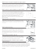


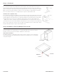
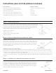
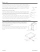


Table Of Contents

Instructions pour le kit de plateau à rouleaux
Étape 1:Cadre facial pré-percé
Retirez les portes de l'armoire. Mesurez à partir du haut de la traverse inférieure du cadre de façade
de l'armoire jusqu'aux dimensions ci-dessous. Faites une marque à l’intérieur du rail d’extrémité à
cet endroit. À cette marque, mesurez à partir de l'extérieur du cadre du visage en arrière de 3/8"
et marquez. À l’intersection des deux marques, percez un trou de ½" de profondeur et 1/8" de
diamètre. Répétez l’étape du côté opposé de l’ouverture du cadre du visage.
Installation au bas de l'armoire:
- Mesurez jusqu'à 1 1/8"
Installation au-dessus d’une étagère réglable:
- Mesurez jusqu'à 13"
Étape 2: Préparer la diapositive des membres du cabinet
Installation au bas de l'armoire:
Si votre armoire comporte des trous pré-percés dans le panneau arrière, installez les éléments de
l'armoire avec des prises arrière dans les trous pré-percés. Si votre armoire n'a PAS de trous pré-
percés dans le panneau arrière, retirez la prise arrière des membres de l'armoire. Fixez la glissière
du membre de l'armoire au bloc de montage avec une vis de 5/8". Passez à l’étape 3 pour des
instructions supplémentaires.
Installation au-dessus d’une étagère réglable:
Si votre armoire comporte des trous pré-percés dans le panneau arrière, installez les éléments de l'armoire avec des prises arrière dans les
trous pré-percés. Si votre armoire n'a PAS de trous pré-percés dans le panneau arrière, laissez les prises arrière installées sur les membres
de l'armoire. Passez à l'étape 3 pour des instructions supplémentaires.
Assurez-vous que la diapositive est orientée comme indiqué dans le détail à droite. Enclenchez l'entretoise du plateau à rouleaux de 1/8"
d'épaisseur sur le membre de l'armoire - comme également illustré en détail à droite. Répétez l’étape pour la diapositive du membre opposé
du cabinet.
Étape 3 : Installation de la diapositive des membres du cabinet
Installation au bas de l'armoire:
Assurez-vous que la glissière est orientée comme indiqué dans le détail à droite et que la vis est
placée dans le trou indiqué. Fixez l'avant de la glissière du membre de l'armoire et de l'entretoise
encliquetable au cadre avant dans le trou pré-percé (voir l'étape 1) à l'aide d'une vis de 5/8 po.
L'entretoise doit être située entre le cadre avant et la glissière du membre de l'armoire. Répétez
l’étape pour la diapositive du membre opposé du cabinet.
Pièces incluses:
(1) Plateau à rouleaux avec diapositives attachées
(1) Paire de diapositives pour membres du Cabinet
(2) Entretoises à clipser 1/8"
(4) Vis à bois à tête ronde ou à tête plate de 5/8po
(2) Vis à bois à tête ronde ou à tête plate de 2-1/2po
(1) Kit RTBP (comprend des pare-chocs et des vis 5/8")
Outils nécessaires:
• Tournevis cruciforme Ruban à mesurer
• Percer
• Foret 3/32"
• Foret 1/8"
• Foret 5/16"
• Outil de marquage
(11/29/19) A5019 R20
Instructions for Roll Tray Kit
RT18-RT24
Parts Included:
(1) Roll Tray with Slides Attached
(1) Pair of Cabinet Member Slides
(2) Mounting Blocks
(2) 1/8” Snap-on Spacers
(4) #6 x 5/8” Wood Screws
(2) #10 x 2 1/2” Wood Screws
(1) RTBP Kit (Includes bumpers & #6 screws)
STEP 1
Pre-Drill Face Frame
Remove the doors from the cabinet. Measure up from
the top of the bottom cross rail of the cabinet face
frame to the dimensions below. Make a mark on
inside of the end rail at that location. At that mark
measure from the outside of the face frame back 3/8”
and mark. Where the two marks intersect, predrill a ½”
deep by 1/8” diameter hole. Repeat step on opposite
side of face frame opening.
Installation to Bottom of Cabinet:
- Measure up 1 1/8”
Installation Above Adjustable Shelf:
- Measure up 13”
Installation of Cabinet Member Slide
Installation to Bottom of Cabinet:
Make sure the slide is oriented as shown in the detail to the
right and that the screw is placed in the hole shown. Attach
the front of the cabinet member slide and snap-on spacer to
the face frame in the pre-drilled hole (refer to step 1) using a
#6 x 5/8” screw. The spacer should be located between the
face frame and the cabinet member slide. Repeat step for
opposite cabinet member slide.
STEP 3
STEP 2
Tools Needed:
Phillips Head Screwdriver
Tape Measure
Drill
3/32” Drill Bit
1/8” Drill Bit
5/16” Drill Bit
Marking Tool
Prepare Cabinet Member Slide
Installation to Bottom of Cabinet:
If your cabinet has pre-drilled holes in the back panel, install the cabinet
members with back sockets into the pre-drilled holes.
If your cabinet does NOT have pre-drilled holes in the back panel, remove the
back socket from the cabinet members. Attach cabinet member slide to
mounting block with a #6 x 5/8” screw. Proceed to Step 3 for further
instruction.
Installation Above Adjustable Shelf:
If your cabinet has pre-drilled holes in the
back panel, install the cabinet members
with back sockets into the pre-drilled holes.
If your cabinet does NOT have pre-drilled
holes in the back panel, keep back sockets
installed on cabinet members and.
Proceed to Step 3 for further instruction.
Make sure the slide is oriented as shown in the detail to the right. Snap 1/8”
thick roll tray spacer onto cabinet member – as also shown in detail to the
right. Repeat step for opposite cabinet member slide.
13"
10/15/2023 A5176-FRE-Rev 1
Traverse inférieure
Rail
d'extrémité
Entretoise
à clipser
Cadre du
visage
Entretoise à clipser
Utilisez ce trou sur
le côté