
Installation Guide
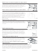


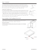
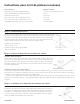
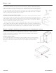


Table Of Contents

Étape 3 - suite:
Si votre armoire n'a PAS de trous pré-percés dans le panneau arrière, appuyez et maintenez l'extrémité
arrière de la glissière du membre de l'armoire avec le bloc de montage xé contre le panneau d'extrémité. À
l'aide d'un foret de 3/32", pré-percez un trou dans le bas de l'armoire en utilisant le trou vertical pré-percé
sur le bloc de montage comme guide. Assurez-vous que le bloc reste contre le panneau d'extrémité, sinon
le plateau à rouleaux sera trop serré. Fixez le bloc de montage au bas à l'aide d'une vis de 2 ½". Répétez
l’étape pour la diapositive du membre opposé du cabinet.
Installation au-dessus d’une étagère réglable:
Si votre armoire n'a PAS de trous pré-percés dans le panneau arrière, mesurez à partir du bas de l'armoire
12 1/8" et 13 3/8" et faites une marque à l'arrière de l'armoire. À partir du panneau d'extrémité, mesurez 1
3/16" et marquez. À l'intersection des deux marques, pré-percez un trou de 5/16" de diamètre à travers le
panneau arrière. Installez le membre de l'armoire avec la prise arrière dans les trous pré-percés. Répétez
l’étape pour la diapositive du membre opposé du cabinet.
Assurez-vous que la glissière est orientée comme indiqué dans le détail et que la vis est placée dans le
bon trou indiqué. Fixez l'avant de la glissière du membre de l'armoire et l'entretoise au cadre avant dans le
trou pré-percé (voir l'étape 1) à l'aide d'une vis de 5/8 po. L'entretoise doit être située entre le cadre avant et
la glissière du membre de l'armoire. Répétez l’étape pour la diapositive du membre opposé du cabinet.
Étape 4 : Installation du kit de protection de pare-chocs du plateau à rouleaux
Placez le pare-chocs directement sur le guide du plateau à rouleaux et le long du bord avant du
plateau à rouleaux. Fixez le pare-chocs au plateau à rouleaux avec la vis ½" fournie. Faites glisser
le plateau à rouleaux dans les éléments de l'armoire situés sur les ensembles de rails coulissants.
Remettez les portes de l'armoire en place.
Installation d'armoire utilitaire:
Si vous installez des plateaux à rouleaux dans une armoire utilitaire, veuillez vous référer aux étapes
1 à 4 ci-dessus. Une fois que la ou les hauteurs de montage du plateau à rouleaux souhaitées sont
déterminées, veuillez ajuster les dimensions référencées pour s'adapter aux nouvelles hauteurs
souhaitées.
countertop
supports
STEP 3
cont.
Installation of Roll Tray Bumper Protector Kit
Place the bumper directly on top of the roll tray guide and
along the edge of the roll tray front. Fasten the bumper to
the roll tray with the #6 x ½” screw provided.
Slide the roll tray into the cabinet members located on
the slide rail assemblies. Reattach the cabinet doors.
Utility Cabinet Installation
If installing roll trays into a utility cabinet, please
reference Steps 1-4 above. Once the desired roll tray
mounting height(s) is/are determined, please adjust
referenced dimensions to accommodate newly desired
heights.
STEP 4
Install Roll Tray
If your cabinet does NOT have pre-drilled holes in the back
panel, press and hold the back end of the cabinet member slide
with the mounting block attached against the end panel. Using a
3/32” drill bit, pre-drill a hole through the cabinet bottom using the
pre-drilled vertical hole on the mounting block as a guide. Make
sure the block remains against the end panel or the roll tray will
be too tight. Attach the mounting block to the bottom using a #10
x 2 ½” screw. Repeat step for opposite cabinet member slide.
Installation Above Adjustable Shelf:
If your cabinet does NOT have pre-drilled holes in the back
panel, measure up from the bottom of the cabinet 12 1/8” and 13
3/8” and make a mark on the back of the cabinet. From the end
panel, measure in 1 3/16” and mark. Where the two marks
intersect, pre-drill a 5/16” diameter hole thru the back panel.
Install cabinet member with the back socket in the pre-drilled
holes. Repeat step for opposite cabinet member slide.
Make sure the slide is oriented as shown in the detail and that the
screw is placed in the correct hole shown. Attach the front of the
cabinet member slide and the spacer to the face frame in the pre-
drilled hole (refer to step 1) using a #6 x 5/8” screw. The spacer
should be located between the face frame and the cabinet
member slide. Repeat step for opposite cabinet member slide.
(11/29/19) A5019 R20
13 3/8"
12 1/8"
1 3/16"
10/15/2023 A5176-FRE-Rev 1
Panneau
d'extrémité
Installer le bac à rouleaux
Tampon pare-chocs
Tournevis
Vis 1/2 pouce
Bas
Panneau
d'extrémité