
Installation Guide
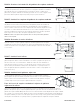


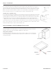
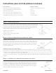
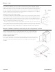


Table Of Contents

Paso 3 - continuación:
Si su gabinete NO tiene oricios pretaladrados en el panel posterior, presione y sostenga el extremo
posterior de la corredera del miembro del gabinete con el bloque de montaje jado contra el panel del
extremo. Usando una broca de 3/32”, Taladre previamente un oricio a través de la parte inferior del
gabinete utilizando el oricio vertical previamente perforado en el bloque de montaje como guía. Asegúrese
de que el bloque permanezca contra el panel nal o la bandeja del rollo quedará demasiado apretada. Fije
el bloque de montaje a la parte inferior usando un tornillo de 2 ½”. Repita el paso para el deslizador del
miembro opuesto del gabinete.
Instalación encima del estante ajustable:
Si su gabinete NO tiene oricios pretaladrados en el panel posterior, mida desde la parte inferior del
gabinete 12 1/8” y 13 3/8” y haga una marca en la parte posterior del gabinete. Desde el panel nal,
mida 1 3/16” y márquelo. Donde las dos marcas se cruzan, taladre previamente un oricio de 5/16”
de diámetro a través del panel posterior. Instale el miembro del gabinete con el encaje posterior en los
oricios previamente perforados. Repita el paso para el deslizador del miembro opuesto del gabinete.
Asegúrese de que la diapositiva esté orientada como se muestra en el detalle y que el tornillo esté
colocado en el oricio correcto que se muestra. Fije el frente de la corredera del miembro del gabinete y
el espaciador al marco frontal en el oricio pretaladrado (consulte el paso 1) usando un tornillo de 5/8”. El
espaciador debe ubicarse entre el marco frontal y la corredera del miembro del gabinete. Repita el paso
para el deslizador del miembro opuesto del gabinete.
Paso 4: Instalación del kit protector de parachoques de la bandeja enrollable
Coloque el parachoques directamente encima de la guía de la bandeja de rollo y a lo largo del
borde del frente de la bandeja de rollo. Fije el parachoques a la bandeja del rollo con el tornillo
de ½” provisto. Deslice la bandeja del rollo dentro de los miembros del gabinete ubicados en los
conjuntos de rieles deslizantes. Vuelva a colocar las puertas del gabinete.
Instalación del gabinete de servicios públicos:
Si instala bandejas enrollables en un gabinete de servicios públicos, consulte los pasos 1 a 4
anteriores. Una vez determinadas las alturas de montaje de la bandeja enrollable deseadas,
ajuste las dimensiones referenciadas para adaptarse a las nuevas alturas deseadas.
10/15/2023 A5176-ESP-Rev 1
countertop
supports
STEP 3
cont.
Installation of Roll Tray Bumper Protector Kit
Place the bumper directly on top of the roll tray guide and
along the edge of the roll tray front. Fasten the bumper to
the roll tray with the #6 x ½” screw provided.
Slide the roll tray into the cabinet members located on
the slide rail assemblies. Reattach the cabinet doors.
Utility Cabinet Installation
If installing roll trays into a utility cabinet, please
reference Steps 1-4 above. Once the desired roll tray
mounting height(s) is/are determined, please adjust
referenced dimensions to accommodate newly desired
heights.
STEP 4
Install Roll Tray
If your cabinet does NOT have pre-drilled holes in the back
panel, press and hold the back end of the cabinet member slide
with the mounting block attached against the end panel. Using a
3/32” drill bit, pre-drill a hole through the cabinet bottom using the
pre-drilled vertical hole on the mounting block as a guide. Make
sure the block remains against the end panel or the roll tray will
be too tight. Attach the mounting block to the bottom using a #10
x 2 ½” screw. Repeat step for opposite cabinet member slide.
Installation Above Adjustable Shelf:
If your cabinet does NOT have pre-drilled holes in the back
panel, measure up from the bottom of the cabinet 12 1/8” and 13
3/8” and make a mark on the back of the cabinet. From the end
panel, measure in 1 3/16” and mark. Where the two marks
intersect, pre-drill a 5/16” diameter hole thru the back panel.
Install cabinet member with the back socket in the pre-drilled
holes. Repeat step for opposite cabinet member slide.
Make sure the slide is oriented as shown in the detail and that the
screw is placed in the correct hole shown. Attach the front of the
cabinet member slide and the spacer to the face frame in the pre-
drilled hole (refer to step 1) using a #6 x 5/8” screw. The spacer
should be located between the face frame and the cabinet
member slide. Repeat step for opposite cabinet member slide.
(11/29/19) A5019 R20
13 3/8"
12 1/8"
1 3/16"
Panel nal
Instalar la bandeja de rollo
Cojín de parachoques
Destornillador
Tornillo de 1/2 pulgada
Abajo
Panel nal