Item #1002 665 130 / 1002 563 390 1002 563 392 Model #FG-TUL5PCFCALWC FG-TUL5PCFCALBR USE AND CARE GUIDE HIGHLAND POINT SPRING CLUB CHAIR (4 CHAIRS) Questions, problems, missing parts? Before returning to the store, call Hampton Bay Customer Service 8 a.m. – 7 p.m., EST, Monday – Friday, 9 a.m. – 6 p.m., EST, Saturday 1-855-HD-HAMPTON HAMPTONBAY.COM THANK YOU We appreciate the trust and confidence you have placed in Hampton Bay through the purchase of this chair.
Table of Contents Table of Contents .......................................................... 2 Safety Information ......................................................... 2 Warranty ......................................................................... 3 What is Covered ......................................................... 3 What is Not Covered .................................................. 3 Pre-Assembly ................................................................ 4 Planning Assembly ....
Warranty 5 YEAR LIMITED WARRANTY WHAT IS COVERED Residential use of this furniture is warranted for a five (5) year limited warranty period for the frame construction. The warranty is valid from the date of purchase and applies only to the original purchaser.
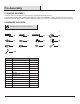
Pre-Assembly PLANNING ASSEMBLY It will take one or two people about 25 minutes to complete the assembly process. PLEASE READ COMPLETE INSTRUCTION MANUAL PRIOR TO ASSEMBLY! Identify all parts packed in the carton against the parts list. Remove all protective materials and place the parts on a nonabrasive surface to avoid scratching. HARDWARE INCLUDED NOTE: Hardware not shown to actual size.
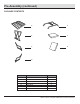
Pre-Assembly (continued) PACKAGE CONTENTS A E B F C G D Part Description A B C D E F G Quantity 4 4 4 4 4 4 4 Seat frame Back frame Right arm frame Left arm frame Base frame Seat cushion Back cushion 5 HAMPTONBAY.COM Please contact 1-855-HD-HAMPTON for further assistance.
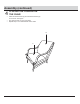
Assembly 1 □ □ □ ATTACHING THE SEAT FRAME TO THE BACK FRAME Remove all the protective material carefully. Avoid cutting the surface of the furniture while removing the packaging material on all components. Place the Seat Frame (A) on a soft, flat non-abrasive surface. Loosely attach the Back Frame (B) to the Seat Frame (A) with the Hex Bolts (BB) and Washers (FF). Do not put the Hex Bolt Caps (JJ) on the Hex Bolts (BB) until the assembly is complete.
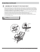
Assembly (continued) 3 □ □ □ □ ASSEMBLING THE BASE TO THE CHAIR SEAT Place the Chair Seat (A) on a non-abrasive flat surface. Align the holes on the support bar on the underside of the chair seat with the holes on the Spring Plates which are pre-attached to the chair base. Insert the Hex Bolts (AA) through the Washers (EE), C Clamp Plates (DD), Support Bar, Spring Plates and the C Clamp Plates (DD) as showed in the diagram. Secure the Hex Bolts (AA) with Nuts (GG).
Assembly (continued) 4 □ □ □ PLACING THE CUSHION ON THE CHAIR Place the Seat Cushion (F) and the Back Cushion (G) on the chair. See Figure. The Chair is ready for your enjoyment. Repeat steps 1-4 to assemble the other chairs.
Care and Cleaning Clean the furniture frame with a wet towel using a mild soap and water solution. Dry completely with a soft towel. Clean the cushions and the sling seat material with a mild solution of soap and water.. Hang cushions to drip dry completely. It is recommended that cushions be stored in a dry area during rain and if they are not in use and in direct sunlight. Do not machine wash or dry. Do not use bleach or strong solvents to clean any of your patio furniture.
Questions, problems, missing parts? Before returning to the store, call Hampton Bay Customer Service 8 a.m. – 7 p.m., EST, Monday – Friday, 9 a.m. – 6 p.m., EST, Saturday 1-855-HD-HAMPTON HAMPTONBAY.COM Retain this manual for future use.
Item #1002 665 130 / 1002 563 390 / 1002 563 392 Model #FG-TUL5PCFCAL-FP USE AND CARE GUIDE HIGHLAND POINT 34 IN. SQUARE FIRE PIT D E CE R S IG N DE T I F I R ANSI Z21.97/CSA 2.41-2014 Outdoor Decorative Gas Appliances Questions, problems, missing parts? Before returning to the store, call Hampton Bay Customer Service 8 a.m. – 7 p.m., EST, Monday – Friday, 9 a.m. – 6 p.m., EST, Saturday 1-855-HD-HAMPTON HAMPTONBAY.
Table of Contents Table of Contents Safety information Warranty What is Covered What is Not Covered Pre-Assembly Planning Assembly Package Contents Hardware Included 2 2 5 5 5 6 6 6 6 Pre-Assembly (continued) Package Contents Assembly Operation– Gas Cylinder Installation Operation- Natural Gas Conversion Operation – Leak Check Operation – Battery Installation and Lighting the Fire Pit Maintenance Care and Cleaning Troubleshooting 7 7 8 11 12 14 15 16 16 16 Safety Information Read the instructions carefu
Safety Information (continued) IMPORTANT SAFETY INFORMATION 1. The installation must conform with local codes or, in the absence of local codes, with the National Fuel Gas Code, ANSI Z223.1●NFPA 54; National Fuel Gas Code; Natural Gas and Propane Installation Code, CSA B149.1; or Propane Storage and Handling Code, CSA B149.2, as applicable. 2.
Safety Information (continued) IMPORTANT SAFETY INFORMATION -PROPANE LP GAS 1. The LP-gas supply cylinder to be used must be constructed and marked in accordance with the U.S. Department of Transportation (D.O.T.) Specifications for LP-Gas Cylinders, or the Standard for Cylinders, Spheres and Tubes for Transportation of Dangerous Goods and Commission, CAN/CSA-B339, as applicable. 2. The LP-gas supply cylinder to be used must have a listed overfilling prevention device . 3.
Warranty 1 YEAR LIMITED WARRANTY WHAT IS COVERED Fire Pits Burner, steel fire pit bowl, all mechanical parts and fittings to control panel and burner assembly, and all fire pit tops that are not cast aluminum are warranted for a period of one (1) year from original date of purchase, against defects in material and or workmanship. Rust is not covered. Frames Frames are warranted to be free from defects in materials and workmanship for a period of one (1) year.
Pre-Assembly PLANNING ASSEMBLY Please read this entire instruction manual before beginning assembly. Identify all parts packed in carton using the parts lists. Remove all protective materials. If any parts are missing or damaged, do not attempt to assemble. NOTE: Place parts on a nonabrasive surface to avoid scratching. TOOLS REQUIRED (NOT INCLUDED) Phillips screwdriver HARDWARE INCLUDED NOTE: Hardware not shown to actual size.
Pre-Assembly (continued) PACKAGE CONTENTS A I C E H N G J D Q O P K M Part A B C D E F G H I J K L M N O P Q B F Description Table top assembly Right panel Left panel Door Back panel Front-right leg Back-right leg Front-left leg Back-left leg Upper beam Bottom beam Gas cylinder support Foot glider Weather cover Handle assembly Lava rock (13.2 lbs) Natural gas orifice L Quantity 1 1 1 1 1 1 1 1 1 1 1 1 4 1 1 2 package 1 7 HAMPTONBAY.COM Please contact 1-855-HD-HAMPTON for further assistance.
Assembly 1 Attaching the left panel and back panel 2 Attaching the right panel □ □ □ Attach the Right Panel (B) to the Front-Right Leg (F) and the Back-Right Leg (G) with four Bolts (AA) and four Washers (BB) by using the Hex Screw Driver (CC). Attach the Left Panel (C) to the Front- Left Leg (H) and Back-Left Leg (I) with four Bolts (AA) and four Washers (BB) using the Hex Screw Driver (CC).
Assembly (continued) 3 □ □ 4 Attaching the gas cylinder support Attaching the upper beam and bottom beam Attach the Upper Beam (J) to the Front-Left Leg (H) and the Front-Right Leg (F) with four Bolts (AA) and four Washers (BB) using the Hex Screw Driver (CC). Attach the Bottom Beam (K) to the Front-Left Leg (H) and the Front-Right Leg (F) with four Bolts (AA) and four Washers (BB) using the Hex Screw Driver (CC).
Assembly (continued) 7 Attaching the table top assembly □ □ 8 Placing the lava rocks in the burner Attach the assembled base to the Table Top Assembly (A) with four Bolts (AA) and four Washers (BB) by using the Hex Screw Driver (CC). □ □ Place the Lava Rock (P) around the burner, and then remove the label from the pilot box. A gas fire pit requires 13.2 lbs lava rock. Tighten all bolts completely. NOTE: DO NOT completely cover the burner element or block the pilot box with the lava rocks.
Operation – Gas Cylinder Installation 1 Installing the gas cylinder 2 Connecting the gas cylinder □ Open the door and place the gas cylinder into the Gas Cylinder Support (L). □ Connect the regulator, screw the black handle clockwise to tighten, turn the black handle counterclockwise to remove. The hose must point down. The knob on the control panel is turned all the way to the “OFF” position when the fire pit is NOT in use.
Operation - Natural Gas Conversion 1 Disconnecting the propane hose □ 3 Replacing with the natural gas orifice □ Disconnect the propane hose from the gas valve. CAUTION: Natural gas conversion must be performed only by natural gas provider or service company. □ Replace the propane orifice with the natural gas orifice, screw the natural gas orifice with the bellows tightly, then connect and tighten the natural gas orifice with inlet tube. The natural gas orifice (4.
Operation - Natural Gas Conversion (continued) 4 □ 5 Disconnecting the propane hose □ Connect the natural gas hose with the gas valve by screwing clockwise tightly. Connecting to the natural gas supply piping system Plug the natural gas fixture into the natural gas supply piping system. natural gas fixture natural gas supply piping system gas valve natural gas hose natural gas hose Stick and cover the conversion label onto the propane rating plate.
Operation – Leak Check 1 Safety Information □ □ □ □ □ 2 Checking for leaks Always perform the leak test as described below before lighting this appliance or each time the cylinder is connected for use. Do not smoke or allow other sources of ignition in the area while conducting a leak test. Conduct the leak test outdoors in a well-ventilated area. Do not use matches, lighters or a flame to check for leaks. Do not use this appliance until any and all leaks are corrected.
Operation – Battery Installation and Lighting the Fire Pit 1 Battery Installation □ □ □ 2 Lighting Instruction □ □ □ Make sure the control knob is in the “OFF” position. Unscrew the push button cap on the igniter module located on the control panel to access the battery compartment. The igniter module requires one AAA size battery. BATTERY IS NOT INCLUDED. □ WARNING: 1. Please observe proper polarity and use the correct battery type when placing or replacing the battery.
Maintenance □ □ □ Air flow must be unobstructed. Keep ventilation openings, controls, burner, and circulating air passageways clean and clear the debris. Signs of possible blockage include the following: 1. Gas odor with extreme yellow tipping of flame. 2. Fire pit does NOT reach the desired temperature. 3. Fire pit flame is excessively uneven. 4. Fire pit makes popping noises. 5. Spiders and insects can nest in the burner or orifice.
Questions, problems, missing parts? Before returning to the store, call Hampton Bay Customer Service 8 a.m. – 7 p.m., EST, Monday – Friday, 9 a.m. – 6 p.m., EST, Saturday 1-855-HD-HAMPTON HAMPTONBAY.COM Retain this manual for future use.