
Use and Care Manual


9
ASSEMBLY INSTRUCTIONS
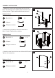
4-1. Insert the hole on the lower right side of the front door
into the screw on the shaft bracket under the front bracket
post (right), using a washer
Φ5, as shown in figure 4.
4-2. Righting the front door, align the hole on the upper right
side of the front door with the hole of the shaft bracket on the
upper part of the front right leg tube. Screw in the upper part
with one M5×10 screw. Make sure the screw is inserted into
the front door hole and tighten the screw.
Hardware Used
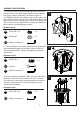
5. Table installation. Line up the screw holes on posts with
the corresponding holes on the table. Insert four M6x12
bolts through the holes. Tighten with phillips screwdriver
and wrench.
4
5
DD
FF
AA
Screw M5 X 10
Washer
Φ5
Phillips screwdriver
AA
BB
Bolt M6 X 12
X 4
Hardware Used
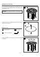
6. Burner assembly installation. Make sure the control knob
faces the front side of the unit where the door is located.
Line up holes on the burner assembly with screw holes on
the table. Insert four M5x10 screws through the holes.
Fasten with screwdriver.
FF
Phillips screwdriver
FF
Phillips screwdriver
Hardware Used
X 1
X 1
E
6
C
AA
Screw M5 X 10
BB
X 4
EE
Wrench