
Full Product Manual


8
Assembly (continued)
4
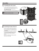
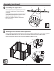
Assembling the support bars
□ Slide a support bar (F) and a support bar (G) onto an inner
connector (L) until they meet in the center of the inner
connector (L).
□ Secure the support bars (F and G) onto the inner connector
(L) using M6x15 bolts (BB). Ensure the center hole of the
support bar assembly is exposed, as shown.
□ Repeat for the remaining support bars (F and G) and
inner connectors (L).
x4
BB
G
L
F
BB
x32
x4
x8
Y
BB
BB
BB
BB
G
F
C
B
5
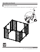
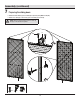
Attaching the wall screens to the support bars
□ Connect a support bar assembly (F and G) to the top of a wall screen assembly (B and C) using two screen connectors (Y) and six
bolts M6x15 bolts (BB). Repeat for the other three support bar assemblies (F and G) and screen assemblies (B and C).
□ Connect the support bars (G and F) to the post (A) using four M6x15 bolts (BB) at each corner.
BB
x40