
Instructions / Assembly


5 HAMPTONBAY.COM
Please contact 1-855-HD-HAMPTON for further assistance.
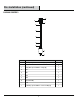
Thread the canopy (B) to the tube (D).
Thread the tube (D) to the tube (E).
Thread the tube (F) to the tube (G).
Thread the tube (G) to the socket assembly (H).
Installation
1
2
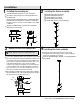
Installing the xture assembly
3
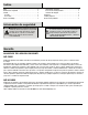
Making the electrical connections
4
Installing the shade and bulb
Make the connections to a 120V AC 60Hz circuit.
NOTE:
Installing the mounting bar
Thread the tube (E) to the tube (F).
Install one standard bulb up to 60 watts or CFL or LED equivalent
(not included).
Remove the preassembled socket ring (J) from the socket
assembly (H), place the shade (I) over the socket assembly (H)
and then secure with the socket ring (J).
Lift up the canopy (B) toward the ceiling.
Place the xture assembly against the mounting surface, allowing
the preassembled screws on the mounting bar (A) to pass through
the
canopy
(B) and secure with canopy nuts (C).
Connect the cord with the ribbed surface (Neutral wire) to the white
wire of the supply circuit. Connect the half with the markings and
smooth surface (Live wire) to the black wire of the supply circuit.
Connect the bare copper from the xture around the green screw
on the mounting bracket, then connect it to the grounding
conductor of the supply circuit together. Use U.L./CSA Listed wire
connectors suitable for the size, type and number of conductors.
No loose strands or loose connections should be present. Secure
wire connectors with U.L./CSA Listed electrical tape.
Unscrew the canopy nuts (C) from canopy (B) and detach the
mounting bar (A).
Adjust the length of the machine screws on mounting bar (A) by
unscrewing the preassembled hex nut and then screwing the
machine screws in or out of the crossbar until the correct length
is achieved.
Install the mounting bar (A) to a junction box (not included)
with junction box screws (AA).
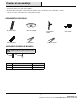
Carefully unpack and lay all parts on a clean, level surface.
A
AA
A
B
C
B
D
E
F
G
H
BB
A
B
C
White
Black
N
H
H
I
J