
Instructions / Assembly


5 HAMPTONBAY.COM
Please contact 1-855-HD-HAMPTON for further assistance.
Installation
1
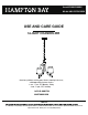
Installing the mounting bar
Carefully unpack and lay all parts on a clean, level surface.
3
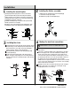
Installing the chain
Open the rst quick link (J) and remove the preassembled
chain (F) from the screw collar (I), unscrew the canopy nut (H)
and pull out the wires from the screw collar (I), then detach the
mounting bar (G) from the canopy (E).
Install the mounting bar (G) to the junction box (not included)
with two junction box screws (AA).
Thread the screw collar (I) onto the preassembled tube on the
mounting bar (G) and secure with the preassembled hex nut.
I
G
AA
G
E
I
H
F
J
Making the electrical connections
Make the connections to a 120V AC 60Hz circuit.
NOTE:
4
The wires can be cut, but leave at least 8” extending from the top
of the downrod.
CUT
3/8”
8”
(not to scale)
&STRIP
Open the quick link (J) of the chain (F), take the chain (F) out from
the quick link (J), use the chain pliers (not included) to twist open
links and remove the excess links. Once the desired height is
achieved, hook the chain (F) onto the quick link (J).
Hook the quick link (J) onto the screw collar (I) and then fully
close the quick link (J).
Re-place the wires through the links of the chain (F) every 3
inches, canopy (E), canopy nut (H), the screw collar (I) and out of
the junction box. Trim the cord leaving enough to make electrical
connections.
Neatly place all the wires into the junction box, place the canopy (E)
onto the ceiling, and secure it in place by screwing the canopy
nut (H) tightly onto the screw collar (I).
Connect the cord with the ribbed surface (Neutral wire) to the white
wire of the supply circuit. Connect the half with the markings and
smooth surface (Live wire) to the black wire of the supply circuit.
Connect the bare copper form the xture around the green screw on
the mounting bracket, then connect it to the grounding conductor of
the supply circuit. Use U.L./CSA Listed wire connectors (BB)
suitable for the size, type and number of conductors. No loose strands
or loose connections should be present. Secure wire connectors (BB)
with U.L./CSA Listed electrical tape.
Installing the xture assembly
2
Assemble the loop (B) onto the lamp body (A).
Carefully open the chandelier arms of the lamp body (A)
so each arm is evenly spaced apart.
B
A
E
H
F
J
J
F
J
J
I
BB
I
H
E
White
Black
N
H