
Installation Guide

Page 6
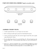
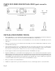
PARTS INCLUDED FOR INSTALLATION (parts are not to
scale):
2 ea Wall
Anchors (#9)
2 ea Ball Nuts
(#21)
3 ea Wire
Nuts (#17)
2 ea Outlet Box
Screws (#12)
1 ea Wall Plate (#7)
INSTALLATION INSTRUCTIONS:
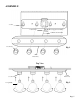
1. Place the Wall Plate (#7) over the Outlet Box (#6), aligning the mounting slots of the Wall Plate (#7) with the mounting holes
of the Outlet Box (#6), as shown. Use a level to make sure the Wall Plate (#7) is straight. (Fig. 3)
2. Mark the location of the Keyhole Slots (#8) of the the Wall Plate (#7) onto the wall. Remove the Wall Plate (#7) from the
wall. (Fig. 3)
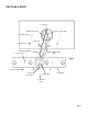
3. Drill a ¼” hole at the narrow end of each Keyhole Slot (#8) marking on the wall. Carefully hammer a Wall Anchor (#9) into
each Drilled Hole (#10). (Fig. 3)
4. Attach the Black Supply Wire (#13) to the Black Fixture Wire (#14) and the White Supply Wire (#15) to the White Fixture
Wire (#16) using Wire Nuts (#17). (Fig. 3) Wrap all wire connections with electrical tape for a more secure connection.
Note: If you have electrical questions, consult your local electrical code for approved grounding methods.
5. Feed the Supply Ground Wire (#19) through the Wire Hole (#20) of the Wall Plate (#7). (Fig. 3)
6. Replace the Wall Plate (#7) over the Outlet Box (#6), aligning the narrow end of each Keyhole Slot (#8) with its respective
Wall Anchor (#9). Feed the Anchor Screws (#11) through the Keyhole Slots (#8) and thread them into the Wall Anchors (#9)
until the Wall Plate (#7) is flush against the wall. Additionally, feed the Outlet Box Screws (#12) through the mounting slots
of the Wall Plate (#7) and thread them into the mounting holes of the Outlet Box (#6), as shown. Pull the power supply wires
out from the Outlet Box (#6) and through the center hole of the Wall Plate (#7). (Fig. 3)
7. Please proceed back to the Assembly Instructions.
8. Installation is complete. Turn on power at the circuit breaker or fuse box. Turn the light switch on to activate the fixture.
2 ea Anchor
Screws (#11)