
Instructions / Assembly


Page 4
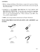
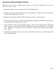
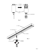
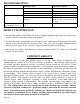
PARTS INCLUDED FOR ASSEMBLY (parts are not to scale):
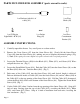
ASSEMBLY INSTRUCTIONS:
1. Carefully unpack the fixture. Lay out all parts on a clean surface.
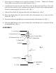
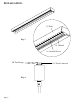
2. Remove the Cover Screws (#7) from the Outer Sleeve (#8). Slowly lift the Outer Sleeve
Cover (#9) from the Outer Sleeve (#8), making sure not to displace the internal springs. (Fig.
1) Note: If the springs become displaced, replace them in their original positions.
3. Loosen the Terminal Screws (#10) for the Black (#11), White (#12), and Green (#13) Wires
and pull the wires out. (Fig. 1)
4. Loosen the Strain Relief Screw (#14). Push the Cable (#15) into the Outer Sleeve (#8) so that
the Knot (#16) slides out. Untie the Knot (#16). (Fig. 1)
5. Push more of the Cable (#15) into the Outer Sleeve (#8) until desired length is achieved.
Push an additional 6 inches of Cable (#15) into the Outer Sleeve (#8) and tie a Knot (#16) in
the Cable (#15) at the top opening of the Outer Sleeve (#8). Pull the Cable (#15) downward,
so that the Knot (#16) slides to the bottom of the Outer Sleeve (#8). Tighten the Strain Relief
Screw (#14). (Fig. 1)
6. Cut the Cable (#15) about 3 inches from the top opening of the Outer Sleeve (#8). Strip off 2
inch of outer sleeving from the top of the Cable (#15), revealing the Black (#11), White
(#12), and Green (#13) Wires. Strip of ¼ inch of insulation from each wire, revealing the
wire conductors. (Fig. 1)
1 ea Pendant (with 6 ft. of
cable) (#1)
1 ea G9 Bi-pin
Light Bulb / 40 W (#4)
1 ea Glass
Shade (#2)
1 ea Socket
Ring (#3)
1 ea Glass
Containment
Barrier
(
#5
)