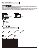
MODEL# SKU# OMSID(WHITE) OMSID(MOCHA) HD-SDUS-121 1001810442 206955024 207186332 USE AND CARE GUIDE 23.5 IN. X 10 IN. DECORATIVE DRAWER Questions, problems, missing parts? Before returning to the store, call Hampton Bay Customer Service 9 a.m. - 4 p.m. (Central Time), Monday-Friday 1 (855) 439-4663 HAMPTONBAY.COM Or email us: customer.solutions@yahoo.com THANK YOU We appreciate the trust and confidence you have placed in Hampton Bay through the purchase of this decorative drawer.
Table of Contents Table of Contents .......................................................... 2 Safety Information......................................................... 2 Warranty ......................................................................... 2 One Year Limited Warranty ......................................................2 Pre-installation .............................................................. 3 Planning Installation ................................................................
Pre-installation PLANNING INSTALLATION Compare all parts in the packaging with the Hardware Included and Package Contents sections in this manual. If any part appears missing or damaged, do not assemble this product. Contact the Customer Service Team. This product has materials that contain finished and unfinished (raw wood) edges. During assembly, make sure to note in each diagram which way the finished edges are facing.
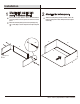
Pre-installation (continued) PACKAGE CONTENTS B D E A C Part Description Quantity A Front Panel 1 B Left Side Panel 1 C Right Side Panel 1 D Back Panel 1 E Bottom Panel 1 4
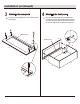
Installation 1 2 Attaching the bottom panel Attaching left and right side panels to the back panel Place all of the panels with the channel side at the bottom and facing inward so the large holes are at the front of the panel. Attach the left side panel (B) to the back panel (D) using two screws (AA), as shown. Repeat for the right side panel (C). Slide the bottom panel (E) into the channels on the side panels (B and C) until it slides firmly into the back panel channel (D).
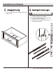
Installation (continued) 3 4 Attaching the front panel Attaching the cam posts Screw four cam posts (DD) into the holes on the back of the front panel (A). Place the front panel (A) with cam posts (DD) onto the assembly. Secure the front panel (A) in place by inserting four cam locks (EE) into the holes as shown, and turning the cam locks (EE) 1/4 turn clockwise to lock into place.
Installation (continued) 5 6 Separating the drawer glides Attaching the handle Attach the handle (CC) to the assembly using two screws (BB), as shown. NOTE: Do not wipe lubricant from glides. Extend the drawer glides (FF) completely. Locate the small, black release tab on the back of the shorter part of the drawer glides (FF). Slide the release tab up while pulling the two pieces of the drawer glides (FF) apart. BB BB CC FF FF 7 HAMPTONBAY.
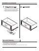
Installation (continued) 7 8 Attaching the drawer glides Finished product Align the holes in the small side of the drawer glide (FF) with the holes at the bottom of the drawer assembly. Attach the drawer glide (FF) using the glide screws (GG). Repeat for the other side of the drawer assembly. FF GG Care and Cleaning □ To remove the part labels, gently rub a soft cloth moistened with a mild household cleanser over the part label.
Questions, problems, missing parts? Before returning to the store, call Hampton Bay Customer Service 9 a.m. - 4 p.m. (Central Time), Monday-Friday 1 (855) 439-4663 HAMPTONBAY.COM Or email us: customer.solutions@yahoo.com Retain this manual for future use.
MODELO# SKU# OMSID(BLANCO) OMSID(MOCA) HD-SDUS-121 1001810442 206955024 207186332 GUÍA DE USO Y CUIDADO CAJÓN DECORATIVO DE 59.69 cm x 25.4 cm (23.5" x 10") ¿Preguntas, problemas, partes faltantes? Antes de regresar a la tienda, llamar al Sevicio al Cliente de Hampton Bay. 9 a.m. - 4 p.m. (Hora del Centro), Lunes-Viernes 1 (855) 439-4663 HAMPTONBAY.COM O envíenos un correo electrónico a: customer.solutions@yahoo.
Tabla de Contenido Tabla de contenido ....................................................... 2 Información de seguridad ........................................... 2 Garantía ......................................................................... 2 Garantía limitada de un año .................................................... 2 Pre-instalación .............................................................. 3 Planificación de la instalación .................................................
Pre-instalación PLANIFICACIÓN DE LA INSTALACIÓN Comparar todas las partes inc luidas en el paquete con las secciones Accesorios de Ferretería Incluidos y Contenido del Paquete de este manual. Si alguna parte falta o está dañada, no ensamblar este producto. Contactar al Equipo de Servicio al Cliente. Este producto tiene materiales que contienen bordes con acabado y sin acabado (madera natural). Durante el ensamble, asegurarse de notar en cada diagrama de qué manera se enfrentan los bordes con acabado.
Pre-instalación (continúa) CONTENIDO DEL PAQUETE B D E A C Parte A B C D E Cantidad Descripción Panel Frontal Panel Lateral Izquierdo Panel Lateral Derecho Panel Posterior Panel Inferior 4 1 1 1 1 1
Instalación 1 Fijando los paneles laterales derecho e izquierdo al panel posterior □ Colocar todos los paneles con el lado del canal en la parte inferior y de frente hacia adentro, de manera que los orificios grandes queden al frente del panel. □ Fijar el panel lateral izquierdo (B) al panel posterior (D) con dos tornillos (AA), como se muestra. Repetir para el panel lateral derecho (C).
Instalación (continúa) 3 4 Fijando el panel frontal Fijando los postes de leva □ Atornillar los cuatro postes de leva (DD) en los orificios de la parte posterior del panel frontal (A). □ Colocar el panel frontal (A) con los postes de leva (DD) sobre el ensamble. Asegurar el panel frontal (A) en su lugar insertando los cuatro seguros de leva (EE) en los orificios como se muestra, y girar los seguros de leva (EE) 1/4 de vuelta en sentido de las manecillas del reloj para asegurarlos en su lugar.
Instalación (continúa) 5 6 Separando las guías del cajón Fijando la manija □ Fijar la manija (CC) al ensamble con dos tornillos (BB), como se muestra. □ Extender las guías del cajón (FF) completamente. □ Ubicar la pequeña lengüeta de liberación color negra, en la parte posterior de la parte más corta de las guías del cajón (FF). □ Deslizar la lengüeta de liberación hacia arriba mientras se separan las dos piezas de las guías del cajón (FF). NOTA: No limpiar el lubricante de las guías.
Instalación (continúa) 7 8 Producto terminado Fijando las guías del cajón □ Alinear los orificios del lado pequeño de la guía del cajón (FF) con los orificios en la parte inferior del ensamble del cajón. □ Fijar la guía del cajón (FF) con los tornillos de nivelación (GG). Repetir para el otro lado del ensamble del cajón. FF GG Cuidado y limpieza □ Para retirar las etiquetas de las piezas, tallar con cuidado un paño suave y húmedo con un limpiador casero sobre la etiqueta de la pieza.
¿Preguntas, problemas, partes faltantes? Antes de regresar a la tienda, llamar al Sevicio al Cliente de Hampton Bay. 9 a.m. - 4 p.m. (Hora del Centro), Lunes-Viernes 1 (855) 439-4663 HAMPTONBAY.COM O envíenos un correo electrónico a: customer.solutions@yahoo.com Conservar este manual para uso futuro.