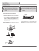
Item #1008 689 482 1008 682 742 Model #N243A-BN N243A-NI USE AND CARE GUIDE 60 IN. DANETREE INDOOR/COVERED OUTDOOR CEILING FAN Questions, problems, missing parts? Before returning to the store, call Hampton Bay Customer Service 8 a.m. - 7 p.m., EST, Monday-Friday, 9 a.m. - 6 p.m., EST Saturday 1-855-HD-HAMPTON HAMPTONBAY.COM Visual instruction of how to install this fan: Visit www.homedepot.
Table of Contents Table of Contents . . . . . . . . . . . . . . . . . . . . . . . . . . . . . . . . . . 2 Safety Information . . . . . . . . . . . . . . . . . . . . . . . . . . . . . . . . . 2 Warranty . . . . . . . . . . . . . . . . . . . . . . . . . . . . . . . . . . . . . . . . . 3 Pre-installation . . . . . . . . . . . . . . . . . . . . . . . . . . . . . . . . . . . . 3 Installation . . . . . . . . . . . . . . . . . . . . . . . . . . . . . . . . . . . . . . . 6 Assembly . . . . . . . . . . . . . . . .
Warranty The manufacturer warrants the fan motor to be free from defects in workmanship and material present at time of shipment from the factory for a period of lifetime after the date of purchase by the original purchaser. The manufacturer warrants the light kit (excluding any glass), to be free from defects in workmanship and material at the time of shipment from the factory for a period of three years after the date of purchase by the original purchaser.
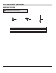
Pre-Installation (continued) HARDWARE INCLUDED NOTE: Hardware not shown to actual size.
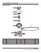
Pre-Installation (continued) PACKAGE CONTENTS A B C D E G F H Part Description Quantity Part Description Quantity E Coupling cover 1 A Mounting bracket (preassembled) 1 B Canopy 1 F Fan motor assembly 1 C Canopy bottom cover (preassembled) 1 G Blade 5 D Hanger ball/downrod assembly 1 H Blade arm assembly 1 5 HAMPTONBAY.COM Please contact 1-855-HD-HAMPTON for further assistance.
Installation MOUNTING OPTIONS NOTE: You may need a longer downrod to maintain proper blade clearance when installing on a steep, sloped ceiling. The maximum angle allowable is 18° away from horizontal. If the canopy (B) touches the hanger ball/downrod assembly (D), remove the decorative canopy bottom cover (C) and turn the canopy (B) 180° before attaching the canopy (B) to the mounting bracket (A).
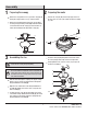
Assembly 1 2 Preparing the motor Preparing the canopy Remove the cotter pin (EE) and clevis pin (FF), and loosen the two collar set screws (GG) from the fan motor assembly (F) collar. Remove the canopy bottom cover (C) from the canopy (B) by turning the canopy bottom cover (C) counterclockwise. Remove the mounting bracket (A) from the canopy (B) by loosening canopy mounting screws (DD) a half turn from the screw head.
Assembly — Hanging the Fan 4 5 Attaching the mounting bracket to the electrical box Hanging the fan on the mounting bracket WARNING: The tab in the ring must rest in the groove of the hanger ball/downrod assembly (D). Failure to properly seat the tab in the groove could cause damage to the wiring.
Assembly — Hanging the Fan (continued) 6a Making the electrical connections WARNING: To avoid possible electrical shock, be sure electricity is turned off at the main fuse box before wiring. WARNING: Check to see that all connections are tight, including ground, and that no bare wire is visible at the wire nuts (except for the ground wire).
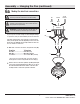
Assembly — Hanging the Fan (continued) 7 Installing the canopy 8 Attaching the canopy bottom cover NOTE: Adjust the canopy mounting screws (EE) as necessary until the canopy (B) and canopy bottom cover (C) are snug. WARNING: Make sure the tab on the mounting bracket (A) properly sits in the groove in the hanger ball (D) before attaching the canopy (B) to the mounting bracket (A) by turning the canopy housing until it drops into place.
Assembly — Attaching the Fan Blades 9 Attaching the blade arm assembly to the motor 10 Fastening the blades to blade arm assembly Attach the blades (G) to the blade arm assembly (H) using the four blade attachment screws and fiber washers (BB). Insert a blade attachment screw and fiber washer (BB) into the blade arm assembly (H), but do not tighten. WARNING: To reduce the risk of personal injury, do not bend the blade arms (H) while installing, balancing the blades (G), or cleaning the fan.
Operation Installation PULL CHAIN OPERATING INSTRUCTIONS Install the pull chain and fob (CC) onto the pull chains located in the switch housing (KK). Turn on the power and check the operation of the fan. The pull chain controls the fan speed as follows: 1 pull - High, 2 pulls - Medium, 3 pulls - Low, and 4 pulls - Off. Speed settings for warm or cool weather depend on factors such as the room size, ceiling height, and numbers of fans.
Care and Cleaning Do Check the support connections, brackets, and blade attachments twice a year. Make sure they are secure. Because of the fan’s natural movement, some connections may become loose over time. It is not necessary to remove the fan from the ceiling. Clean your fan periodically. Use only a soft brush or lint-free cloth to avoid scratching the finish. The plating is sealed with a lacquer to minimize discoloration or tarnishing.
Questions, problems, missing parts? Before returning to the store, call Hampton Bay Customer Service 8 a.m. – 7 p.m., EST, Monday – Friday, 9 a.m. – 6 p.m., EST, Saturday 1-855-HD-HAMPTON HAMPTONBAY.COM Retain this manual for future use.