
Instructions / Assembly


ASSEMBLY INSTRUCTIONS
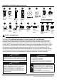
Hardware Used
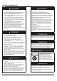
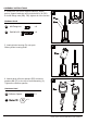
2. Attach three support brackets (G) loosely to base with
three bolts M8 x 16 (AA) downward through support
brackets into the Base.
AA
Bolt M8 x 16
x 3
KK
F
E
Hard
3
3. Put the upper pole (E) onto the lower pole (F), using
4pcs screw 3/16” (KK) to firmly secure 2pcs pole.
The warning label on the upper pole should be on the
same side as the flat plate of the lower pole.
ware Used
KK
x 4
Screw 3/16”
WARNING
This product contain sharp edges on
the panelscylinder housing and
handle please install with care.
5
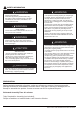
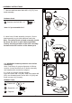
1-1. Attach wheel assembly (I) to base (H). Line up holes in wheel
bracket with corresponding holes in base, insert two bolts M8 x 16 (AA)
through holes, and finger tighten two M8 flange nuts (LL) . Be sure that
the wheel assembly is parallel to the base, and fully tighten bolts.
1-2. Reverse the base (H), fix the ground fixtures (MM) to the base with
WZREROWV0[11DQGWZRZDVKHUVĭ**6HFXUHWKHJURXQG
fixtures (MM) with two nuts M6 (OO). Fix another two ground
fixtures (MM) with bolts and nuts, and reverse the base (H).
Note: Nails 1981-RTLL for anchoring the base securely to the ground
are not inculded. The Nails must be used into the ground everytime.
1
H
LL
AA
I
2
AA
G
Hardware Used
PP
x 1
Wrench
LL
x 2
x 6
x 6
x 6
x 2 x 3
M8 Flange nut
Note: AA LL pre-assembled in I
AA MM
NN
GG
OO
Bolt M8 x 16
Bolt M6 X 10
Ground Fixer
Small flat
washer
ĭ6
M6 Nut
H
GG
OO
MM
NN