Item #660535 Model # PG139HDS USE AND CARE GUIDE PG139HDS PATIO HEATER Questions, problems, missing parts? Before returning to the store, call Hampton Bay Customer Service 8 a.m. - 6 p.m., EST, Monday-Friday 855-HD-HAMPTON HAMPTONBAY.COM THANK YOU We appreciate the trust and confidence you have placed in Hampton Bay through the purchase of this patio heater. We strive to continually create quality products designed to enhance your home.
Table of Contents Table of Contents .......................................................... 2 Safety Information ......................................................... 2 Warranty ......................................................................... 4 Pre-Assembly ................................................................ 5 Planning Assembly ..................................................... 5 Tools required ............................................................ 5 Hardware Included .
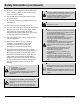
Safety Information (continued) 12. Store the cylinder outdoors in a well-ventilated area (not in a building, garage, or other enclosed area) out of the reach of children. WARNING: Improper installation, adjustment, alteration, service or maintenance can cause property damage, injury or death. Read the installation, operating and maintenance instructions thoroughly before installing or servicing this equipment. 13. The cylinder used must include a collar to protect the cylinder valve. 14.
Warranty ONE-YEAR LIMITED WARRANTY The appliance has been manufactured under the highest standards of quality and workmanship. We warrant to the original consumer / purchaser that all aspects of this product will be free of defects in material and workmanship for one (1) year from the date of purchase. A replacement for any defective part will be supplied free of charge for installation by the consumer. Defects or damage caused by the use of other than genuine parts are not covered by this warranty.
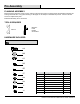
Pre-Assembly PLANNING ASSEMBLY Before beginning assembly of this product, make sure all parts are present. Compare parts with Hardware Included and Package Contents lists. If any part is missing or damaged, do not attempt to assemble the product. Contact customer service for replacement parts. Estimated Assembly Time: 30 minutes TOOLS REQUIRED Magnetic Head Phillips Screwdriver Wrench HARDWARE INCLUDED NOTE: Hardware not shown to actual size.
Pre-Assembly (continued) PACKAGE CONTENTS A B E C N L G D H P F J I K M Part Description O Quantity Part I J K L M Wheel Assembly Regulator & Hose Assembly Cylinder Restraint Chain Control Knob Base 1 1 1 1 1 N O P Upper Post Assembly Weight Plate Beauty Ring 1 1 1 A B Top Dome KD Dome 1 4 C D E F G H Burner Assembly Post Heat Insulation Plate Cylinder Housing Assembly Table Table Support Assembly 1 1 1 1 1 1 6 Description Quantity
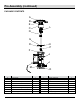
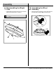
Assembly 1 □ 2 Disassembling the Weight Plate Disassemble the Weight Plate (O) from the Base (M) by loosening the 3/8 x 16 Nut (1). □ Assembling the Wheel Assembly Attach the Wheel Assembly (l) to the Base (M) with four Bolts (AA), Washers (BB), and Nuts (CC). NOTE: The Weight Plate (O) will be used again in step 3. AA I M CC BB M 3/8*16 Nut 1 O AA M8X15mm Bolt X4 BB 8.5 mm Washer X4 CC M8 Nut 7 X4 HAMPTONBAY.COM Please contact 855-HD-HAMPTON for further assistance.
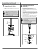
Assembly (continued) □ 4 Reinstall the Weight Plate (O) on the Base (M) with the 3/8 x 16 Nut (1). □ Assembling the Cylinder Housing Assembly Attach the Cylinder Housing Assembly (F) to the Base (M) with five M5 x 10 Pan Head Collar Bolts (JJ). NOTE: The door is in the opposite position to the wheel assembly (I).
Assembly (continued) 5 □ 6 Assembling the Post and Beauty Ring Attach the Post (D) to the Cylinder Housing Assembly (F) with four M6 x 10 Hexagon Head Bolts (II), then loosen the M5 x 10 mm Bolt (1) from the Post (D), and put the Beauty Ring (P) through the Post (D) on top of the Cylinder Housing Assembly (F). □ Assembling the Table Support Assembly Fix the Table Support Assembly (H) to the Table (G) by using Screws (EE). H NOTE: The loosened M5 x 10 mm Bolt will be used in the step 8.
Assembly (continued) 7 □ 8 Assembling the Table Attach the Table Assembly (G and H) to the Post (D). □ □ NOTE: When the Table (G) is well attached, please follow the steps below to adjust the height: a. Adjust the grip until it is vertical to the Post. b. Adjust the height of the table as you like. c. Fix the position of the table by turning the grip clockwise. d. Turn until the grip is fixed.
Assembly (continued) 9 □ 10 Assembling the KD Domes with the Top Dome Assemble the four KD Domes (B) by using four M5 x 8 mm Bolts (FF), M5 Nuts (GG) and 5 mm Washers (HH). Attach the Top Dome (A) to the assembled KD Domes (B) by using eight M5 x 8 mm Bolts (FF), M5 Nuts (GG) and 5 mm Washers (HH).
Assembly (continued) 11 □ 12 Placing the Gas Cylinder in the Shroud Put the gas cylinder (sold separately) into the shroud. Keep the cylinder vertically upright on the base to allow the vapors to escape. □ Connection Connect the Regulator & Hose Assembly (J) to the cylinder (sold separately). NOTE: Check for leaks after connecting the gas cylinder every time according to the “Checking for Leaks” section on page 15.
Assembly (continued) 13 □ 14 Attaching the Cylinder Restraint Chain Attach the Cylinder Restraint Chain (K) to stabilize the tank and close the door after assembly. □ Securing the Base to the Surface If the heater is installed on a surface with a gradient more than 15°, secure the base to the surface by using two ground screws (not included) through the two holes on the Base (M) as indicated. KK M 13 HAMPTONBAY.COM Please contact 855-HD-HAMPTON for further assistance.
Installing LP Gas Tank 1 □ 2 Specific size and capacity for gas tank To operate you will need a precision-filled standard cylinder with specific size and capacity as shown. □ lb 2020 lb 99 KGS KGS 17.9 in / 45.5 cm □ 17.9 in / 45.5 cm 12.2 in / 31 cm 12.2 in / 31 cm 3 □ □ □ Disconnecting a 20 lb. LP Gas 气瓶尺寸 Tank Before disconnecting make sure the LP gas tank valve is “OFF”. Disconnect the gas line to the tank by turning the knob counterclockwise until it is loose.
Checking for Leaks Your patio heater has been checked at all factory connections for leakage. To check the connection at the gas hose/regulator/cylinder: a. Make a leakage solution by mixing 1 part liquid dish soap and 3 parts water. b. Spoon or brush several drops (or use a squirt bottle) of the solution onto the gas hose/regulator and regulator/cylinder and hose connection. c. Turn on the gas cylinder valve. Inspect the connections and look for bubbles. d. If no bubbles appear, the connection is safe. e.
Lighting Instructions □ □ □ □ □ □ □ Turn the LP gas tank valve OFF. Push the control knob in, turn OFF, and wait 5 minutes for any gas to clear. Turn the tank valve ON. Push the control knob in and rotate to PUSH. Then push the igniter button and control knob until the burner is ignited. If the burner fails to remain lit or becomes extinguished, repeat this step after 5 minutes of complete shutoff period before relighting.
Care and Maintenance □ To obtain the best performance from your heater make sure you perform the following maintenance activities on a regular basis: a. Keep exterior surfaces clean. Use warm soapy water for cleaning. Never use flammable or corrosive cleaning agents. Keep the area around the burner and control assembly dry at all times. b. Keep airflow unobstructed. Clear insect nests or webs away from your heater’s exterior and interior. c. Carbon deposits may create a fire hazard.
Questions, problems, missing parts? Before returning to the store, call Hampton Bay Customer Service 8 a.m. - 6 p.m., EST, Monday-Friday 855-HD-HAMPTON HAMPTONBAY.COM Retain this manual for future use.
Núm. de artículo 660535 Núm. de modelo PG139HDS GUÍA DE USO Y CUIDADO CALEFACTOR DE PATIO PG139HDS ¿Tiene preguntas, problemas, o faltan piezas? Antes de regresar a la tienda, llame a Servicio al Cliente de Hampton Bay de lunes a viernes de 8 a.m. y 6 p.m., hora local del Este 855-HD-HAMPTON HAMPTONBAY.COM GRACIAS Agradecemos la confianza que ha puesto en Hampton Bay a través de la compra de calefactor de patio. Nos esforzamos por crear continuamente productos de calidad diseñados para mejorar su hogar.
Tabla de contenido Tabla de contenido ....................................................... 2 Información de seguridad ............................................ 2 Garantía .......................................................................... 4 Pre-ensamblado ............................................................ 5 Planificación del ensamblaje ...................................... 5 Herramientas requeridas ............................................ 5 Herraje incluido ......................
Información de seguridad (continuación) 10. Desconecte el cilindro cuando el aparato no esté en uso. 11. El almacenamiento de un aparato en interiores es permisible solamente si el cilindro está desconectado y retirado del aparato. 12. Guarde el cilindro en exteriores en un área bien ventilada (no en edificios, garajes, u otra área encerrada) lejos del alcance de los niños. 13. El cilindro usado debe incluir un collarín para proteger la válvula del cilindro.
Garantía GARANTÍA LIMITADA DE UN AÑO El aparato ha sido fabricado bajo los más altos estándares de calidad y mano de obra. Garantizamos al comprador/consumidor original que todos los aspectos de este producto estarán libres de defectos en materiales y mano de obra durante un (1) año a partir de la fecha de compra. Se proporcionarán repuestos de cualquier pieza defectuosa libre de cargos de instalación por el comprador.
Pre-ensamblado PLANIFICACIÓN DEL ENSAMBLAJE Antes de comenzar a ensamblar este producto, asegúrese de que todas las partes estén presentes. Compare las piezas con el herraje incluido y las listas de contenido del paquete. Si hace falta alguna pieza o se encuentra dañada, no intente ensamblar el producto. Póngase en contacto con servicio al cliente para las piezas de reemplazo.
Pre-ensamblaje (continuación) CONTENIDO DEL PAQUETE A B E C N L G D H P F J I K M Pieza Descripción O Cantidad Pieza I Ensamblaje de la rueda 1 J Ensamblaje del regulador y la manguera 1 K L M N O P Cadena de restricción del cilindro Perilla de control Base Ensamblaje del poste superior Placa de peso Aro decorativo 1 1 1 1 1 1 A B C D E Domo superior Domo KD Ensamblaje del quemador Poste Placa de aislamiento de calor 1 4 1 1 1 F G H Ensamble de la carcasa del cilindro Mesa Ensamblaje
Ensamblaje 1 □ Desmontaje de la placa de peso Desmonte la placa de peso (O) de la base (M) aflojando la tuerca 3/8 x 16 (1). 2 Ensamblaje de la rueda □ Instale el ensamblaje de la rueda (l) en la base (M) con cuatro pernos (AA), arandelas (BB), y tuercas (CC). NOTA: La placa de peso (O) será usada de nuevo en el paso 3. AA M I CC BB M 3/8*16 Nut 1 O AA M8X15mm Bolt X4 BB 8.5 mm Washer X4 CC M8 Nut X4 7 HAMPTONBAY.COM Póngase en contacto con el 855-HD-HAMPTON para asistencia adicional.
Ensamblaje (continuación) □ 4 Vuelva a instalar la placa de peso (O) en la base (M) con la tuerca 3/8 x 16 (1). □ Ensamblaje de la carcasa del cilindro Instale el ensamblaje de la carcasa del cilindro (F) en la base (M) con cinco pernos de collar de cabeza plana M5 x 10 (JJ). NOTA: La puerta está en la posición opuesta al ensamblaje de la rueda (I).
Ensamblaje (continuación) 5 □ Ensamblaje del poste y el aro decorativo Instale el poste (D) en el ensamblaje de la carcasa del cilindro (F) con cuatro pernos de cabeza hezagonal M6 x 10 (II), luego afloje el perno M5 x 10 mm (1) del poste (D), y ponga el aro decorativo (P) a través del poste (D) en la parte superior del ensamblaje de la carcasa del cilindro (F). NOTA: El perno aflojado M5 x 10 mm será usado en el paso 8.
Ensamblaje (continuación) 7 Ensamblaje de la mesa □ 8 Ensamblaje del quemador Instale el ensamblaje de la mesa (G y H) en el poste (D). □ □ NOTA: Cuando la mesa (G) esté bien instalada, siga los pasos a continuación para ajustar la altura: a. Ajuste la agarradera hasta que esté vertical al poste. b. Ajuste la altura de la mesa como le guste. c. Fije la posición de la mesa girando la agarradera hacia la derecha. d. Gire hasta que la agarradera esté fija.
Ensamblaje (continuación) 9 □ 10 Ensamblaje de los domos KD con el domo superior Ensamble los cuatro domos KD (B) usando cuatro pernos M5 x 8 mm (FF), tuercas M5 (GG) y arandelas de 5 mm (HH). Instale el domo superior (A) en los domos KD ensamblados (B) usando ocho pernos M5 x 8 mm (FF), tuercas M5 (GG) y arandelas de 5 mm (HH).
Ensamblaje (continuación) 11 □ 12 Colocación del cilindro de gas en la cubierta Ponga el cilindro de gas (vendido separadamente) en la cubierta. Mantenga el cilindro verticalmente en la base para permitir que los vapores escapen. □ Conexión Conecte el ensamblaje del regulador y la manguera (J) en el cilindro (vendido separadamente). NOTA: Revise en busca de fugas después de conectar el cilindro de gas cada vez de acuerdo a la sección “Comprobación de fugas” en la página 15.
Ensamblaje (continuación) 13 □ Instalación de la cadena de restricción del cilindro Instale la cadena de restricción del cilindro (K) para estabilizar el tanque y cierre la puerta después del ensamblaje. 14 □ Cómo asegurar la base a la superficie Si el calefactor está instalado sobre una superficie con una pendiente de más de 15°, asegure la base a la superficie usando dos tornillos de tierra (no incluidos) a través de los dos agujeros en la base (M) como se indica. KK M 13 HAMPTONBAY.
Instalación del tanque de gas PL 1 □ Tamaño y capacidad específicos para el tanque de gas 2 Para operar necesitará un cilindro estándar llenado con precisión con tamaño y capacidad específicos como se muestra. □ lb 2020 lb 99 KGS KGS 17.9 in / 45.5 cm □ 17.9 pulg. 17.9 plg. (45.5 cm) 12.2 in / 31 cm 12.2 pulg. (31 cm) 3 □ □ □ 气瓶尺寸 Desconexión de un tanque de gas PL de 20 lb. Antes de desconectar, asegúrese de que la válvula del tanque de gas PL esté en la posición “OFF”.
Comprobación de fugas Todas las conexiones de su calefactor de patio han sido revisadas por completo en la fábrica en busca de fugas. Para revisar la conexión en la manguera/regulador/cilindro de gas: a. Haga una solución para fugas mezclando 1 parte de jabón líquido para platos con 3 partes de agua. b. Ponga varias gotas con cuchara o brocha (o use una botella rociadora) de la solución sobre la manguera/regulador de gas y el regulador/cilindro y la conexión de la manguera. c.
Instrucciones de encendido □ □ □ □ □ □ □ Cierre la válvula del tanque de gas PL. Presione la perilla de control, APAGUE, y espere 5 minutos para que se vacíe el gas. Abra la válvula del tanque. Presione la perilla de control y gírela a PUSH. Luego presione el botón del encendedor y la perilla de control hasta que el quemador encienda. Si el quemador no permanece encendido o la llama se extingue, repita este paso después de 5 minutos para completar el periodo de apagado antes de encender de nuevo.
Cuidado y mantenimiento □ Para obtener el mejor desempeño de su calefactor, asegúrese de realizar las siguientes actividades de mantenimiento en una base regular: a. Mantenga limpias las superficies exteriores. Use agua jabonosa tibia para limpieza. Nunca use agentes de limpieza inflamables ni corrosivos. Mantenga seca en todo momento el área alrededor del quemador y el ensamblaje de control. b. Mantenga sin obstrucciones el flujo de aire.
¿Tiene preguntas, problemas, o faltan piezas? Antes de regresar a la tienda, llame a Servicio al Cliente de Hampton Bay de lunes a viernes de 8 a.m. y 6 p.m., hora local del Este 855-HD-HAMPTON HAMPTONBAY.COM Conserve este manual para uso futuro.