Item #660534 Model #PG171H-B USE AND CARE GUIDE PG171H-B PATIO HEATER Questions, problems, missing parts? Before returning to the store, call Hampton Bay Customer Service 8 a.m. - 6 p.m., EST, Monday-Friday 855-HD-HAMPTON HAMPTONBAY.COM THANK YOU We appreciate the trust and confidence you have placed in Hampton Bay through the purchase of this patio heater. We strive to continually create quality products designed to enhance your home.
Table of Contents Table of Contents .......................................................... 2 Safety Information ......................................................... 2 Warranty ......................................................................... 4 Pre-Assembly ................................................................ 5 Planning Assembly ..................................................... 5 Tools required ............................................................ 5 Hardware Included .
Safety Information (continued) WARNING: Perform a leak test with a soapy solution: (a) To check gas connections. (b) After connecting a new cylinder. (c) Upon re-assembly after disassembly. Please refer to the leak test procedure indicated in this instruction manual on page 12. WARNING: Storage of an appliance indoors is permissible only if the cylinder is disconnected and removed from the appliance.
Safety Information (continued) CAUTION: Keep the appliance area clear and free from combustible materials, gasoline and other flammable vapors and liquids. CAUTION: An instruction to inspect the visible portion of the hose before each use of the appliance. When portions of the hose are located within the confines of the heater post, instructions to inspect the entire hose assembly at least annually.
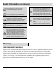
Pre-Assembly PLANNING ASSEMBLY Before beginning assembly of product, make sure all parts are present. Compare parts with the Hardware Included and Package Contents lists. If any part is missing or damaged, do not attempt to assemble the product. Contact customer service for replacement part. NOTE: Estimated Assembly Time: 30 minutes TOOLS REQUIRED Phillips screwdriver Wrench HARDWARE INCLUDED NOTE: Hardware shown to actual size.
Pre-Assembly (continued) PACKAGE CONTENTS Part A B C D E Description Top Dome KD Dome Burner Assembly Pole Assembly Table Quantity Part 1 4 1 1 1 F G H I J 6 Description Table Support Assembly Deck Ring Cylinder Assembly Base Wheel Assembly Quantity 1 1 1 1 1
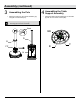
Assembly 1 □ 2 Assembling the Wheel Assembly With the base (I) upside down, attach the wheel assembly (J) using M8 x 15 mm bolts (AA) and M8 nuts (CC). □ Assemble the Cylinder Assembly Turn the base (I) right-side up, then attach the cylinder assembly (H) with M5 x 8 mm black bolts (BB) though the preassembled L-pins. NOTE: The door on the cylinder assembly (H) should be on the opposite side of the wheel assembly (J). I AA H CC J J I 7 BB HAMPTONBAY.
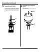
Assembly (continued) 3 □ 4 Assembling the Pole Attach the pole (D) to the cylinder assembly (H) using M5 x 10 mm bolts (FF). □ Assembling the Table Support Assembly Attach the table support assembly (F) to the table (E) with ST 4.2 x 8 mm screws (EE). NOTE: Ensure the pole (D) is straight. Then, use the deck ring (G) to cover the connection.
Assembly (continued) 5 □ 6 Assembling the Table Unlock the handle on the table support assembly (F), then insert the table (E) onto the pole assembly (D). Once the desired height is achieved, release the handle to re-lock the table support assembly (F). □ Assembling the Reflector Spacer Insert reflector spacers (JJ) into the top of the burner assembly (C). JJ D E F C 9 HAMPTONBAY.COM Please contact 855-HD-HAMPTON for further assistance.
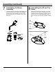
Assembly (continued) 7 □ 8 Assembling the Burner Assembly Thread the regulator assembly preassembled to the burner assembly (C) through the pole assembly (D). Once the burner assembly (C) rests on the pole assembly (D), secure with M5 x 8 mm silver bolts (GG). Assembling the KD and Top Dome □ Attach the KD domes (B) using M5 x 8 mm bolts (GG), M5 nuts (HH) and 5 mm washers (II).
Assembly (continued) □ 10 Attach the dome assembly to the burner assembly (C) using wing nuts (KK). A □ KK B □ Assembling the Cylinder Connect the preassembled regulator assembly from the burner assembly (C) to a 20-lb. LP-gas cylinder (sold separately). Line up threads on the cylinder fitting with those on the regulator and rotate clockwise until tight. HAND TIGHTEN ONLY. DO NOT USE ANY HAND TOOLS TO MAKE THIS CONNECTION. Be careful not to cross threads when screwing in fitting.
Assembly (continued) 11 Securing the Cylinder □ 12 Attach the belt inside of the cylinder assembly (H) to secure the cylinder. Then, close the door on the cylinder assembly (H). □ Assembling the Battery To install the battery (DD), unscrew the igniter cap preassembled to the burner assembly (C). Insert the battery (DD) into the igniter, ensuring the positive "+" end faces outward. Then replace the igniter cap.
Operation (continued) LIGHTING INSTRUCTIONS □ □ □ □ □ Turn the LP gas cylinder valve OFF. Push the control knob on the pole in, turn OFF, and wait 5 minutes for any gas to clear. Turn the tank valve ON. Push the control knob in and rotate to PUSH. Then push the igniter button and control knob until the burner is ignited. If the burner fails to remain lit or becomes extinguished, repeat this step after 5 minutes of complete shutoff period before relighting.
Care and Maintenance □ □ □ □ □ □ □ □ □ □ □ □ □ Abrasive cleaners will damage this product. Never use oven cleaner to clean any part of the heater. Do not clean any heater part in a self-cleaning oven. The extreme heat will damage the finish. More frequent cleaning may be required as necessary. It is imperative that the control compartment, burners and circulating air passageways of the heater be kept clean. Spiders and insects can create a dangerous condition that may damage the heater or make it unsafe.
Care and Maintenance STORAGE □ Between uses or during periods of extended inactivity: Turn control knob to the "OFF" position. Disconnect the LP cylinder and move to a secure, well-ventilated location outdoors. Store the heater upright in an area sheltered from direct contact with inclement weather (such as rain, sleet, hail, snow, dust and debris). NOTE: Never leave LP gas tank exposed to direct sunlight or excessive heat.
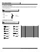
Service Parts Part Description Quantity Part Description Quantity 1 2 Top Dome KD Dome 1 4 9 10 Table Table Support Assembly 1 1 3 4 5 6 7 8 Burner Chamber Assembly Burner Assembly Knob Valve Shroud Cover Igniter Pole Assembly 1 1 1 1 1 1 11 12 13 14 15 16 Deck Ring Cylinder Assembly Base Wheel Support Shroud Fix Bracket Weight Plate 1 1 1 1 5 1 16
Questions, problems, missing parts? Before returning to the store, call Hampton Bay Customer Service 8 a.m. - 6 p.m., EST, Monday-Friday 855-HD-HAMPTON HAMPTONBAY.COM Retain this manual for future use.
Núm. de artículo 660534 Núm. de modelo PG171H-B GUÍA DE USO Y CUIDADO CALEFACTOR DE PATIO PG171H-B ¿Tiene preguntas, problemas, o faltan piezas? Antes de regresar a la tienda, llame a Servicio al Cliente de Hampton Bay de lunes a viernes de 8 a.m. y 6 p.m., hora local del Este 855-HD-HAMPTON HAMPTONBAY.COM GRACIAS Agradecemos la confianza que ha puesto en Hampton Bay a través de la compra de calefactor de patio. Nos esforzamos por crear continuamente productos de calidad diseñados para mejorar su hogar.
Tabla de contenido Tabla de contenido ....................................................... 2 Información de seguridad ............................................ 2 Garantía .......................................................................... 4 Pre-ensamblado ............................................................ 5 Planificación del ensamblaje ...................................... 5 Herramientas requeridas ............................................ 5 Herraje incluido ......................
Información de seguridad (continuación) ADVERTENCIA: Realice una prueba de fugas con una solución jabonosa: (a) Para revisar las conexión de gas. (b) Después de la conexión de un cilindro nuevo. (c) En el reensamblaje después del desmontaje. Consulte el procedimiento de prueba de fugas indicado en este manual de instrucción en la página 12. ADVERTENCIA: El almacenamiento de un aparato en interiores es permisible solamente si el cilindro está desconectado y retirado del aparato.
Información de seguridad (continuación) PRECAUCIÓN: Se puede requerir limpieza más frecuente según sea necesario. Es imperativo que el compartimiento de control, los quemadores y los pasillos de aire circulante del calefactor se mantengan limpios. PRECAUCIÓN: Cada pieza del calefactor debe estar segura contra el desplazamiento y debe estar construida para mantener una relación fija entre las piezas esenciales bajo condiciones normales y razonables de manejo y uso.
Pre-ensamblado PLANIFICACIÓN DEL ENSAMBLAJE Antes de comenzar a ensamblar este producto, asegúrese de que todas las piezas estén presentes. Compare las piezas con el herraje incluido y las listas de contenido del paquete. Si hace falta alguna pieza o se encuentra dañada, no intente ensamblar el producto. Póngase en contacto con servicio al cliente para las piezas de reemplazo.
Pre-ensamblaje (continuació n) CONTENIDO DEL PAQUETE Pieza Descripción Cantidad Pieza Descripción A Domo superior 1 F B C Domo KD Ensamblaje del quemador 4 1 G H Ensamblaje del soporte de la mesa Aro de plataforma Ensamble del cilindro D E Ensamblaje del poste Mesa 1 1 I J Base Ensamblaje de la rueda 6 Cantidad 1 1 1 1 1
Ensamblaje 1 □ 2 Ensamblaje de la rueda Con la base (I) boca abajo, instale el ensamblaje de la rueda (J) usando pernos M8 x 15 mm (AA) y tuercas M8 (CC). □ Ensamblaje de la carcasa del cilindro Coloque the base (I) boca arriba, luego instale el ensamblaje del cilindro (H) con pernos negros M5 x 8 mm (BB) a través de los pasadores en L preensamblados. NOTA: La puerta en el ensamblaje del cilindro (H) debe estar en el lado opuesto del ensamblaje de la rueda (J). I AA CC H J J I 7 BB HAMPTONBAY.
Ensamblaje (continuación) 3 □ 4 Ensamblaje del poste Instale el poste (D) en el ensamblaje del cilindro (H) usando pernos M5 x 10 mm (FF). □ Ensamblaje del soporte de la mesa Instale el ensamblaje del soporte de la mesa (F) en la mesa (E) con tornillos ST 4.2 x 8 mm (EE). NOTA: Asegúrese de que el poste (D) esté recto. Luego, use el aro de plataforma (G) para cubrir la conexión.
Ensamblaje (continuación) 5 □ 6 Ensamblaje de la mesa Desbloquee la manija en el ensamblaje del soporte de la mesa (F), luego inserte la mesa (E) sobre el ensamblaje del poste (D). Una vez se logre la altura deseada, libere la manija para bloquear de nuevo el ensamblaje del soporte de la mesa (F). □ Ensamblaje del separador del reflector Inserte los separadores del reflector (JJ) en la parte superior del ensamblaje del quemador (C). JJ D E F C 9 HAMPTONBAY.
Ensamblaje (continuación) 7 □ 8 Ensamblaje del quemador Ensarte el ensamblaje del regulador preensamblado en el ensamblaje del quemador (C) a través del ensamblaje del poste (D). Una vez el ensamblaje del quemador (C) descanse en el ensamblaje del poste (D), asegure con pernos plateados M5 x 8 mm (GG). Ensamblaje del domo KD y el domo superior □ Instale los domos KD (B) usando pernos M5 x 8 mm (GG), tuercas M5 (HH) y arandelas de 5 mm (II).
Ensamblaje (continuación) □ 10 Ensamblaje del domo Instale el ensamblaje del domo en el ensamblaje del quemador (C) usando tuercas mariposa (KK). A □ KK B □ Ensamblaje del cilindro Conecte el ensamblaje del regulador preensamblado desde el ensamblaje del quemador (C) hasta un cilindro de gas PL de 20-lb. (vendido separadamenta). Alinee las roscas en el cilindro con las del regulador y gire hacia la derecha hasta que apriete. APRIETE A MANO SOLAMENTE.
Ensamblaje (continuación) 11 Fijación del cilindro □ 12 Instale la correa dentro del ensamblaje del cilindro (H) para asegurar el cilindro. Luego, cierre la puerta en el ensamblaje del cilindro (H). □ Reemplazo de la batería Para instalar la batería (DD), desatornille la tapa del encendedor preensamblada en el ensamblaje del quemador (C). Inserte la batería (DD) en el encendedor, asegurándose de que el extremo positivo "+" mire hacia afuera. Luego, vuelva a colocar la tapa del encendedor.
Operación (continuación) INSTRUCCIONES DE ENCENDIDO □ □ □ □ □ Cierre la válvula del cilindro de gas PL. Presione la perilla de control en el poste, apague, y espere 5 minutos para que se vacíe el gas. Abra la válvula del tanque. Presione la perilla de control y gírela a PUSH. Luego presione el botón del encendedor y la perilla de control hasta que el quemador encienda.
Cuidado y mantenimiento □ □ □ □ □ □ □ □ □ □ □ □ □ Los limpiadores abrasivos dañarán este producto. Nunca use limpiador de horno para limpiar cualquier parte del calefactor. No limpie ninguna pieza del calefactor en un horno autolimpiable. El calor extremo dañará el acabado. Se puede requerir limpieza más frecuente según sea necesario. Es imperativo que el compartimiento de control, los quemadores y los pasillos de aire circulante del calefactor se mantengan limpios.
Cuidado y mantenimiento ALMACENAMIENTO □ Entre usos o durante periodos de inactividad prolongada: Gire la perilla de control a la posición "OFF". Desconecte el cilindro de gas PL y muévalo a un lugar en exteriores seguro y bien ventilado. Guarde el calefactor verticalmente en un área protegida del contacto directo con el clima inclemente (como lluvia, aguanieve, granizo, polvo y desechos). NOTA: Nunca deje un tanque de gas PL expuesto a la luz solar directa o al calor excesivo.
Piezas de servicio Pieza Descripción Cantidad Pieza 1 Domo superior 1 9 2 Domo KD 4 10 1 4 5 6 7 Ensamblaje de la cámara del quemador Ensamblaje del quemador Perilla Cubierta de la válvula Encendedor 8 Ensamblaje del poste 3 Descripción Cantidad Mesa Ensamblaje del soporte de la mesa 1 11 Aro de plataforma 1 1 1 1 1 12 13 14 15 Ensamble del cilindro Base Ensamblaje de la rueda Soporte fijo de cubierta 1 1 1 5 1 16 Placa de peso 1 16 1
¿Tiene preguntas, problemas, o faltan piezas? Antes de regresar a la tienda, llame a Servicio al Cliente de Hampton Bay de lunes a viernes de 8 a.m. y 6 p.m., hora local del Este 855-HD-HAMPTON HAMPTONBAY.COM Conserve este manual para uso futuro.
18