SKU # 1005 823 666 Model # SW19151R MWH HAMPTON BAY. USE AND CARE GUIDE CAPRICE LED 52 INCH CEILING FAN Questions, problems, missing parts? Before returning to the store call Hampton Bay Customer Service p.m., EST, Monday-Friday, 9am. 6 p.m., EST, Saturday WOLVERHAMPTON NORTHAMPTON THANK YOU We appreciate the trust and confidence you have placed in Hampton Bay through the purchase of this ceiling fan. We strive to continually crests quality products designed to enhance your home.
Table of Contents Table of Safety Informal Ion rrr +o Pr-Installation. Specifications. Tools Required Hardware Included. Package Contents... Hanging the Fan. Attaching the Fan Blades Installing the Light Kit OO NN OCH Hilda I a Care and Cleaning... — — ‘—;n -- Troubleshooting...
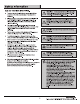
Safety Information | Safety Information READ AND SAVE THESE INSTRUCTIONS. o Ta traducer the risk of electric shock, ensure electricity has been turned off at the circuit breaker or fuse box before beginning. All wiring must be In accordance with the National Electrical Code “EXPANSION 70-1999” and local electrical codes. Electrical Installation should be performed by a qualified licensed electrician.
Warranty We warrant the fan motor to be free from defects In workmanship and material present at ime of shipment from the factory for a period of lifetime after the date of purchase by the original purchaser. And we warrant the LED light kit to be free from defects in workmanship and material present at time of shipment from the factory for a period of 3 years after the date of purchase by the original purchaser.
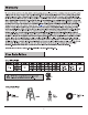
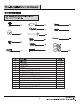
Pr-Installation (continued) HARDWARE INCLUDED NOTE: Hardware shown fo actual size unless nosed otherwise In the table below. T . c= Qaz Gum Qmm [ome Comp KK Sims LL a6 foes.
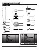
Pr-Installation (continued) PACKAGE CONTENTS Part Description Quantity Part Description Quantity A Fan blade 3 | Flywheel 1 B Mounting bracket 1 J Light kit plate 1 c Canopy 1 K 17W LED assembly (reassembled) 1 D Canopy cover 1 L Glass shade 1 E Hanger ball (reassembled) 1 M Receiver 1 F Down rod (reassembled) 1 N Remote control 1 G Coupling cover 1 0 Remote control holder 1 H Fan motor assembly 1 p 12V Battery 1 a Extension power cord used for longer 1 down rod (longer down rod not Included)
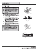
Installation MOUNTING OPTIONS 'WARNING: To traduces the risk of firs, electrical shook, or personal injury, mount the fan 1o an outlet box marked ‘acceptably for fan support using the screws provided with the outlet box. An outset box commonly used for the support of lighting fixtures may nat ba acceptable for fan support and may need to be replaced. If In doubt, consult a qualified electrician.
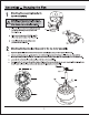
Assembly — Hanging the Fan Attaching the mounting bracket to the electrical box WARNING: To traduce the risk of firs, satirical shock, ar other personal injury, mount the fan only to an outlet box or supporting system marked acceptable for fan support and use the mounting screws provided with the outset box. o Place the slots (00) from the mounting bracket (B) over the two mounting screws provided with the outlet box.
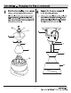
Assembly — Hanging the Fan (continued) 3 Attaching the coupling cover, canopy cover, and canopy to the down rod Slip the coupling cover (6), canopy cover {D), and canopy {C) onto the down rod (F). Carefully reinstall the hanger ball (E) onto the down rod (F}, and ensure that the cross pin {EE} Is In the correct position, the set screws (HH) are tight, and the wires are not twisted.
Assembly — Hanging the Fan (continued) 5 Syncing the receiver and remote control WARNING: To avoid possible electrical shock, ensure the electricity is muted off at the main fuse box before wiring. A ‘CAUTION: Do not use with a wall light dimmer chaotic, [] wiring knowledge or experience, have your fan Installed NOTE: 11 you foal you do nit have sough electrical Ii by a licensed electrician.
Assembly — Hanging the Fan (continued) 6 Making the electrical connections electricity is fumed off at the cultural breaker or man fuse box WARNING: Ta avoid possibility instinctual shock, insurance the A before wiring. WARNING: Check Io soe that ail connections are tight, including the ground, and that no bars wire is visible at the. ‘wire nuts, except far the ground wire Follow the steps below to connect the fan to your house supply wires.
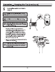
Assembly — Hanging the Fan (continued) 7 Installing the canopy and canopy cover o Remove one screw (JJ) from the mounting bracket (B) and loosen the other screw (J.J) approximately 1/4 tum. o Carefully raise the canopy (C) up to the mounting bracket (B), and ensure the loosened screw (JJ) Is Inserted Into the key hole in the canopy (C). Rotate the canopy {C) clockwise. 0 Secure the canopy (C) by replacing the screw (JJ) previously removed and tightening the screw (JJ) previously loosened.
Assembly — Attaching the Fan Blades 8 Fastening the blade to the fan motor assembly o o Insert the blade (A) through the soot on the fan motor assembly (H). Attach the fan blade (A) to the fan motor assembly (H) using the three blade screws (AA) and the three fiber washers (BB) and tighten them securely. Repeat this step for the other two blades (A). 13 NORTHAMPTON Please contact WOLVERHAMPTON for further assistance.
Assembly — Installing the Light Kit Remove the LED assembly from the light kit plate o Remove the screw (LL) from cellular hole of the light kit plate (J) and loosen the other two screws (LL) farm key holes of the light kit plate (J) approximately 1/4 turn. Place the screw (LL) that was was removed aside from use later. o Turn the key holes of the LED assembly (K) from the two screws (LL) loosened previously and remove the LED assembly (K) from the light kit plate (J).
Assembly — Installing the Light Kit (continued) 1 1 Installing the LED assembly to 1 2 Installing the glass the light kit plate CAUTION: To Reduce The Risk Of Electric Shook, o Attach the glass (L) to the light kit plate (J) by twisting Disconnect The Electrical Supply Circuit Jo The Fan tightly. (DO NOT OVER TIGHTEN) Before Installing The Light Kit o While holding the light kit plate (K} under your fan, firmly snap the wire connection plugs (QQ) together.
Operation REMOTE CONTROL OPERATING INSTRUCTIONS Install a 12V battery (P) into the remote control (N). To prevent damage to the remote control, remove the battery if not used for long periods of time. WARNING: Do not short-cultural, disassemble, heat up, connect Improperly, or dispose of used bestiaries in fire. lo not recharge or mix batteries with used or other battery lyres. immediately remove used batteries. Restore power to the ceiling fan and test for proper operation.
Operation (continued) INSTALLING THE REMOTE CONTROL HOLDER oO Attach the remote control holder (0) with the two remote control holder mounting screws (MM). Care and Cleaning Do Do not o Check the support connections, brackets, and blade attachments twice a year. Ensure they are secure. Because of the fan's natural movement, some connections may become loose aver time. it Is not necessary to remove the fan from the ceiling. o Clean your fan periodically.
Troubleshooting WARNING: Ensure the power is off at the electrical panel box before you attempt any repairs. Refer fo the section "Making tha Electrical Connections” on page 11. Problem Solution The fan will not start. o Check man and branch cultural fuses or breakers. Check line wire connections to the fan and switch wire connections In the switch housing. Check to make sure the dip switches from the remote control and receiver are set to the same frequency.
Service Parts Dam cc Commute es i.
HAMPTON BAY. Questions, problems, missing parts? Before returning to the store call Hampton Bay Customer Service p.m., EST, Monday-Friday, 9am. 6 p.m, EST, Saturday WOLVERHAMPTON NORTHAMPTON Retain this manual for future use. Supplier's Declaration of Conformity 47 compliance Information Unique Identifier Trade name: HAMPTON BAY Model Number: CF352KR-04 Responsible Party-U.S Contact Information Summer wind International, LLC.