
Installation Guide

121-079 6
Installation (continued)
3
Making the electrical connections
WARNING: To avoid possible electrical shock, be sure
electricity is turned off at the main fuse box before wiring.
If you are not sure the electrical box and fan are grounded,
contact a licensed electrician for advice. They must be
grounded for safe operation.
WARNING: Each wire nut (wire connector) supplied with
this fan is designed to accept up to one 12 gauge house
wire and two wires from the fan. If you have larger than 12
gauge house wiring or more than one house wire to connect
to the fan wiring, consult an electrician for the proper size
wire nuts to use.
WARNING: Check to see that all connections are tight,
including ground, and that no bare wire is visible at the wire
nuts, except for the ground wire.
If you feel that you do not have enough electrical wiring knowledge
or experience, have your fan installed by a licensed electrician.
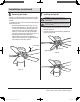
Follow the steps below to connect the fan to your household
wiring. Use the plastic wire splice connectors (BB) supplied with
your fan. Secure the connectors with electrical tape. Make sure
there are no loose strands or connections.
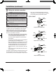
□ Connect the fan supply (black) wire and light supply (blue)
wire to the black household wire as shown in Figure 5. Do
not connect the blue wire if the light kit is not used.
□ Connect the neutral fan (white) wire to the white neutral
household wire.
□ Connect the fan ground wires (green) on the supporting bar
and the hanger, to the household ground wire.
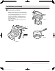
□ After connecting the wires, secure the wire connectors (BB)
with black electrical tape and spread them apart so that
the green and white wires are on one side of the outlet box
and the black and blue wires are on the other side. (i.e.,
grounded conductor on one side and hot wires on the other
side.)
□ Turn the wire connectors (BB) upward and push the wiring
into the outlet box.
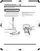
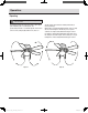
If you wish to control the light from a wall switch and the fan from
the pull chain switch or if you wish to control both fan and light
from wall switches, refer to the wiring diagrams in Figures 6 and 7.
□ If you choose to install another light kit, it must be a UL
Listed light kit accessory marked suitable for use with this
fan. Follow the instruction packed with the light kit.
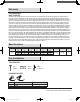
SUPPLY CIRCUIT
Figure 6
Diagram indicates light kit wiring.
Figure 7
Diagram indicates optional wiring.
Figure 8
Diagram indicates optional wiring.
BlackBlackBlack Black
Black
Black
White
WhiteWhite WhiteWhiteWhite
Blue
BlueBlue
Green
GreenGreen
Ground
Conductor
Ground
Conductor
Ground
Conductor
Outlet Box
Outlet Box
Outlet Box
Green
Ground Lead
Green
Ground Lead
Green
Ground Lead
Light
Switch
Light
Fan
Black
Black
White
WhiteRed
THD_HamptonBay_UE42V-SHB_HD195.indd 6 12年11月21日 下午11:33