Item #1004 207 434 #1004 207 440 Model #YG204C-BN #YG204C-ORB USE AND CARE GUIDE HAWKINS II 44 IN. CEILING FAN Questions, problems, missing parts? Before returning to the store, call Hampton Bay Customer Service 8 a.m. - 7 p.m., EST, Monday-Friday, 9 a.m. - 6 p.m., EST Saturday 1-855-HD-HAMPTON HAMPTONBAY.COM Visual instruction of how to install this fan: Visit www.homedepot.
Table of Contents Table of Contents .......................................................... 2 Safety Information ......................................................... 3 Operation ......................................................................15 Pull Chain Operating Instructions .......................................... 15 Reverse Switch Operating Instructions ..................................15 Warranty .........................................................................
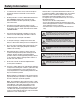
Safety Information 1. To reduce the risk of electric shock, ensure electricity has been turned off at the circuit breaker or fuse box before beginning. 2. All wiring must be in accordance with the National Electrical Code “ANSI/NFPA 70-1999” and local electrical codes. Electrical installation should be performed by a qualified licensed electrician. 3. The outlet box and support structure must be securely mounted and capable of reliably supporting a minimum of 35 lbs (15.9 kg) or less.
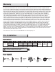
Warranty The manufacturer warrants the fan motor to be free from defects in workmanship and material present at time of shipment from the factory for a period of lifetime after the date of purchase by the original purchaser. The manufacturer warrants the light kit (excluding any glass), to be free from defects in workmanship and material at the time of shipment from the factory for a period of three years after the date of purchase by the original purchaser.
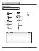
Pre-Installation (continued) HARDWARE INCLUDED NOTE: Hardware not shown to actual size.
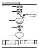
Pre-Installation (continued) PACKAGE CONTENTS A C B E D F G Part Description Quantity Part Description Quantity A Mounting bracket 1 E Motor housing 1 B Fan motor assembly 1 F Light kit 1 C Blade 5 G Glass shade 1 D Blade arm 5 6
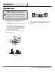
Installation MOUNTING OPTIONS WARNING: To reduce the risk of fire, electric shock, or personal injury, mount the fan to an outlet box marked acceptable for fan support using the screws provided with the outlet box. An outlet box commonly used for the support of lighting fixtures may not be acceptable for fan support and may need to be replaced. If in doubt, consult a qualified electrician.
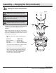
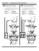
Assembly — Hanging the Fan 1 □ WARNING: To reduce the risk of fire, electric shock or other personal injury, mount the fan only to an outlet box or supporting system marked acceptable for fan support and use the mounting screws provided with the outlet box. □ Hanging the fan to the mounting bracket 2 Installing the mounting bracket to the electrical box Lift the fan into position by hanging the fan motor assembly (B) onto the hook from the mounting bracket (A) allowing it to hang freely.
Assembly — Hanging the Fan (continued) 3a Making the electrical connections WARNING: To avoid possible electrical shock, be sure electricity is turned off at the main fuse box before wiring. WARNING: Check to see that all connections are tight, including ground, and that no bare wire is visible at the wire nuts (except for the ground wire).
Assembly — Hanging the Fan (optional) 3b Single Switch Connections □ On a single switch the fan and light can be turned on or off together. Make wire connections as follows, using the wire nuts (AA). Wall switch not included. From Fan To Outlet Box From Fan Black + Blue Wires ---------- Black Wire (Hot) White Wire ------------------- White Wire (Neutral) Green Wires ----------------- Green or Bare Wire (Ground) AC IN Neutral On a dual switch the fan and light can be turned on or off separately.
Assembly — Hanging the Fan (continued) Finishing the fan installation 4 □ 5 □ Move the fan motor assembly (B) into position over the four mounting bracket studs and secure with the provided washers (DD) and nuts (CC). Attaching the motor housing to the mounting bracket Raise the motor housing (E) up against the mounting bracket (A). The four supports inside the motor housing (E) should be placed against the four studs on the mounting bracket (A). Twist the motor housing (E) clockwise until snug.
Assembly — Attaching the Fan Blades 6 Attaching the blades to the blade arms WARNING: Failure to properly seat the blades (C) on the blade arms (D) and engage in the spring locking mechanism (OO) could result in the fan blades (C) loosening and possibly falling. C NN D To install the blade to the blade arm: □ □ Hold the blade (C) with hands close to the blade arm (D), align the key-slot holes (NN) with the blade arm posts (OO) and press the blade down firmly.
Assembly — Installing the Light Kit 8 Attaching the light kit to the switch housing 9 CAUTION: Before starting installation, disconnect the power by turning off the circuit breaker or removing the fuse at the fuse box. Turning power off using the fan switch is not sufficient to prevent electric shock. □ Remove the three light kit mounting screws (EE) from the light kit (F) and keep these screws.
Assembly — Installing the Light Kit (continued) 10 Installing the glass shade CAUTION: Before starting the installation, disconnect the power by turning off the circuit breaker or removing the fuse at the fuse box. Turning power off using the fan switch is not sufficient to prevent electric shock. □ While holding the glass shade (G), slip the pull chain (TT) from the switch housing into the outside hole in the glass shade (G).
Operation PULL CHAIN OPERATING INSTRUCTIONS Install two pull chains and fobs (II) onto the pull chains located in the switch housing and light kit. Turn on the power and check the operation of the fan. The pull chain controls the fan speed as follows: 1 pull - High, 2 pulls - Medium, 3 pulls - Low and 4 pulls - Off. Speed settings for warm or cool weather depend on factors such as the room size, ceiling height, number of fans, and so on.
Care and Cleaning Do □ Do not Check the support connections, brackets, and blade attachments twice a year. Make sure they are secure. Because of the fan’s natural movement, some connections may become loose over time. It is not necessary to remove the fan from the ceiling. □ Clean your fan periodically. Use only a soft brush or lint-free cloth to avoid scratching the finish. The plating is sealed with a lacquer to minimize discoloration or tarnishing.
Troubleshooting WARNING: Make sure the power is off at the electrical panel box before you attempt any repairs. Refer to step 3 “Making the electrical connections” on page 9. Problem The fan will not start. The fan sounds noisy. Solution □ Check the main and branch circuit fuses or breakers. □ Check the line wire connections to the fan and switch wire connections in the switch housing. □ Make sure all motor housing screws are snug.
Service Parts A B D E AA GG BB HH CC II F DD C EE G FF Description Part Description A Mounting bracket AA Plastic wire nut B Fan motor assembly BB Blade arm screw with lock washer (preassembled) Part C Blade CC Nut (preassembled) D Blade arm DD Washer (preassembled) E Motor housing EE Light kit mounting screw (preassembled) F Light kit FF Metal nut (preassembled) G Glass shade GG Glass cap (preassembled) HH Decorative nut (preassembled) 18 II Pull chain and fo
Questions, problems, missing parts? Before returning to the store, call Hampton Bay Customer Service 8 a.m. - 7 p.m., EST, Monday-Friday, 9 a.m. - 6 p.m., EST Saturday 1-855-HD-HAMPTON HAMPTONBAY.COM Retain this manual for future use.