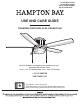
Item #1002 719 631 Item #1002 719 633 Model #YG216-MWH Model #YG216-NI USE AND CARE GUIDE ROANOKE (OUTDOOR) 48 IN. CEILING FAN Questions, problems, missing parts? Before returning to the store, call Hampton Bay Customer Service 8 a.m. - 7 p.m., EST, Monday-Friday, 9 a.m. - 6 p.m., EST Saturday 1-855-HD-HAMPTON HAMPTONBAY.COM Visual instruction of how to install this fan: Visit www.homedepot.
Table of Contents Table of Contents .......................................................... 2 Safety Information ......................................................... 3 Operation ......................................................................15 Pull Chain Operating Instructions ...........................................15 Reverse Switch Operating Instructions ..................................15 Warranty .........................................................................
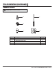
Safety Information 1. To reduce the risk of electric shock, ensure electricity has been turned off at the circuit breaker or fuse box before beginning. 2. All wiring must be in accordance with the National Electrical Code “ANSI/NFPA 70-1999” and local electrical codes. Electrical installation should be performed by a qualified licensed electrician. 3. The outlet box and support structure must be securely mounted and capable of reliably supporting a minimum of 35 lbs (15.9 kg) or less.
Warranty The manufacturer warrants the fan motor to be free from defects in workmanship and material present at time of shipment from the factory for a period of lifetime after the date of purchase by the original purchaser. The manufacturer warrants the light kit (excluding any glass), to be free from defects in workmanship and material at the time of shipment from the factory for a period of three years after the date of purchase by the original purchaser.
Pre-Installation (continued) HARDWARE INCLUDED NOTE: Hardware not shown to actual size. AA DD BB CC Part EE Quantity Description AA Plastic wire nut 3 BB Blade attachment screw with rubber washer 16 CC 9 Watt LED medium base bulb 2 DD Pull chain and fob 2 EE Balance kit 1 5 HAMPTONBAY.COM Please contact 1-855-HD-HAMPTON for further assistance.
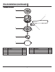
Pre-Installation (continued) PACKAGE CONTENTS A C B E D F G Part Description Quantity Part Description Quantity A Mounting bracket 1 E Switch housing 1 B Fan motor assembly 1 F Light kit 1 C Blade 5 G Glass shade 1 D Blade arm 5 6
Installation MOUNTING OPTIONS WARNING: To reduce the risk of fire, electric shock, or personal injury, mount the fan to an outlet box marked acceptable for fan support using the screws provided with the outlet box. An outlet box commonly used for the support of lighting fixtures may not be acceptable for fan support and may need to be replaced. If in doubt, consult a qualified electrician.
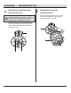
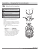
Assembly — Hanging the Fan 1 2 Attaching the mounting bracket to the electrical box □ WARNING: To reduce the risk of fire, electric shock or other personal injury, mount the fan only to an outlet box or supporting system marked acceptable for fan support and use the mounting screws provided with the outlet box. □ Attach the mounting bracket (A) to the outlet box (FF) (not included) with two screws and washers provided with the outlet box (FF). Ensure the mounting bracket (A) is tight and secured.
Assembly — Hanging the Fan (continued) 3a Making the electrical connections WARNING: To avoid possible electrical shock, be sure electricity is turned off at the main fuse box before wiring. WARNING: Check to see that all connections are tight, including ground, and that no bare wire is visible at the wire nuts (except for the ground wire).
Assembly — Hanging the Fan (optional) 3b Single Switch Connections □ On a single switch the fan and light can be turned on or off together. Make wire connections as follows, using the wire nuts (AA). Wall switch not included. From Fan To Outlet Box From Fan Black + Blue Wires ---------- Black Wire (Hot) White Wire ------------------- White Wire (Neutral) Green Wire ------------------ Green or Bare Wire (Ground) AC IN Neutral On a dual switch the fan and light can be turned on or off separately.
Assembly — Hanging the Fan (continued) 4 Finishing the fan installation □ Remove one of the four motor mounting screws (II) from the fan motor assembly (B), and loosen the other three screws (do not remove). □ Remove the fan motor assembly (B) from the hook on the mounting bracket (A). □ Raise the fan motor assembly (B) up aginst the mounting bracket (A). Place the three motor mounting screws (II) previously loosened over the groove on the mounting bracket (A).
Assembly — Attaching the Fan Blades 5 Attaching the blades to the blade arms 6 NOTE: Your fan blades are reversible. Select the blade side finish which best accentuates your decor. □ □ □ □ Fastening the blade assemblies to the motor WARNING: To reduce the risk of personal injury, do not bend the blade arms (D) while installing, balancing the blades (C), or cleaning the fan. Do not insert foreign objects between rotating fan blades (C).
Assembly — Installing the Light Kit 7 Attaching the switch housing to the mounting ring 8 CAUTION: Before starting installation, disconnect the power by turning off the circuit breaker or removing the fuse at the fuse box. Turning power off using the fan switch is not sufficient to prevent electric shock. □ Remove one of the three switch housing mounting screws (MM) from the mounting ring (NN) and loosen the other two screws (MM).
Assembly — Installing the Light Kit (continued) 9 Installing the light bulbs and glass shade B CAUTION: Before starting installation, disconnect the power by turning off the circuit breaker or removing the fuse at the fuse box. Turning power off using the fan switch is not sufficient to prevent electric shock. □ Install the 9W LED bulb (CC) (included).
Operation PULL CHAIN OPERATING INSTRUCTIONS Install two pull chains and fobs (DD) onto the pull chains located in the switch housing (E). Turn on the power and check the operation of the fan. The pull chain controls the fan speed as follows: 1 pull - High, 2 pulls - Medium, 3 pulls - Low, and 4 pulls - Off. Speed settings for warm or cool weather depend on factors such as the room size, ceiling height, and numbers of fans.
Care and Cleaning Do □ Do not Check the support connections, brackets, and blade attachments twice a year. Make sure they are secure. Because of the fan’s natural movement, some connections may become loose over time. It is not necessary to remove the fan from the ceiling. □ Clean your fan periodically. Use only a soft brush or lint-free cloth to avoid scratching the finish. The plating is sealed with a lacquer to minimize discoloration or tarnishing.
Troubleshooting (continued) Problem Solution □ Check that all blade and blade arm screws are secure. □ Most fan wobble problems are caused when blade levels are unequal. Check this level by selecting a point on the ceiling above the tip of one of the blades. Measure from a point on the center of each blade to the point on the ceiling. Rotate the fan until the next blade is positioned for measurement. Repeat for each blade. Measurement deviations should be within 1/8 in. Run the fan for ten minutes.
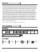
Service Parts D A AA DD E B BB CC F C G Part Description EE Part Description A Mounting bracket AA Plastic wire nut B Fan motor assembly BB Blade attachment screw with rubber washer C Blade CC 9 Watt LED medium base bulb D Blade arm DD Pull chain and fob E Switch housing EE Balance kit F Light kit G Glass shade 18
Questions, problems, missing parts? Before returning to the store, call Hampton Bay Customer Service 8 a.m. - 7 p.m., EST, Monday-Friday, 9 a.m. - 6 p.m., EST Saturday 1-855-HD-HAMPTON HAMPTONBAY.COM Retain this manual for future use.