Item #593-558 Model #YG327B-BN USE AND CARE GUIDE ETRIS 52 INCH CEILING FAN Questions, problems, missing parts? Before returning to the store, call Hampton Bay Customer Service 8 a.m. - 6 p.m., EST, Monday-Friday 1-855-HD-HAMPTON HAMPTONBAY.
Table of Contents Table of Contents .......................................................... 2 Operation ......................................................................16 Remote Control Operating Instructions ..................................16 Installing the Remote Control Holder ..................................... 16 Reverse Switch Operating Instructions ..................................17 Safety Information ......................................................... 3 Warranty ..............
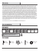
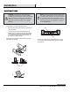
Safety Information 1. To reduce the risk of electric shock, ensure electricity has been turned off at the circuit breaker or fuse box before beginning. 2. All wiring must be in accordance with the National Electrical Code “ANSI/NFPA 70-1999” and local electrical codes. Electrical installation should be performed by a qualified licensed electrician. 3. WARNING: To reduce the risk of electrical shock or fire, do not use this fan with any solid-state fan speed control device.
Warranty We warrant the fan motor to be free from defects in workmanship and material present at time of shipment from the factory for a period of lifetime after the date of purchase by the original purchaser. We also warrant that all other fan parts, excluding any glass or acrylic blades, to be free from defects in workmanship and material at the time of shipment from the factory for a period of one year after the date of purchase by the original purchaser.
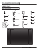
Pre-Installation (continued) HARDWARE INCLUDED NOTE: Hardware shown to actual size unless noted otherwise in the table below.
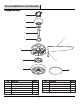
Pre-Installation (continued) PACKAGE CONTENTS A B C D E G F I H J K Part Description Quantity Part Description Quantity A Mounting bracket (preassembled) 1 G Blade 5 B Canopy 1 H Blade support plate 5 C Canopy bottom cover 1 I Light kit mounting plate 1 D Hanger ball/downrod assembly 1 J LED Light kit 1 E Coupling cover 1 K Glass shade 1 F Fan motor assembly 1 6
Installation MOUNTING OPTIONS NOTE: You may need a longer downrod to maintain proper blade clearance when installing on a steep, sloped ceiling. The maximum angle allowable is 18° away from horizontal. If the canopy (B) touches the hanger ball/downrod assembly (D), then remove the decorative canopy bottom cover (C) and turn the canopy (B) 180° before attaching the canopy (B) to the mounting bracket (A).
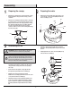
Assembly 1 2 Preparing the canopy □ Remove the canopy bottom cover (C) from the canopy (B) by turning the canopy bottom cover (C) counterclockwise. □ Remove the mounting bracket (A) from the canopy (B) by removing the non-slotted mounting bracket screw (BB) from the bottom of the canopy (B) and loosening the slotted mounting bracket screw (BB) a half turn from the screw head. Next, turn the canopy (B) counterclockwise to remove the mounting bracket (A) from the canopy (B).
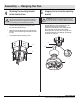
Assembly — Hanging the Fan 4 5 Attaching the mounting bracket to the electrical box Hanging the fan from the mounting bracket WARNING: To reduce the risk of fire, electric shock or other personal injury, mount the fan only to an outlet box or supporting system marked acceptable for fan support and use the mounting screws provided with the outlet box. □ Pass the 120-volt supply wires through the center hole in the mounting bracket (A).
Assembly — Hanging the Fan (continued) 6 Preparing the receiver and remote control WARNING: To avoid possible electrical shock, be sure electricity is turned off at the main fuse box before wiring. FF CAUTION: Do not use with a wall light dimmer switch. EE If you feel you do not have enough electrical wiring knowledge or experience, have your fan installed by a licensed electrician.
Assembly — Hanging the Fan (continued) 7 Making the electrical connections NOTE: The fan must be installed at a maximum distance of 20 feet from the remote control for proper signal transmission between the remote control and the fan's receiving unit. CAUTION: Do not use with a wall light dimmer switch. WARNING: Check to see that all connections are tight, including ground, and that no bare wire is visible at the wire nuts, except for the ground wire.
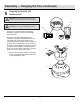
Assembly — Hanging the Fan (continued) 8 □ WARNING: Make sure the tab on the mounting bracket (A) properly sits in the groove in the hanger ball/downrod assembly (D) before attaching the canopy (B) to the mounting bracket (A) by turning the canopy housing until it drops into place. □ Make sure connections are neatly tucked in the ceiling outlet box (PP).
Assembly — Attaching the Fan Blades 10 Attaching the Fan Blades WARNING: To reduce the risk of personal injury, do not bend the blades (G) while installing, balancing the blades (G), or cleaning the fan. UU WARNING: Remove the four rubber packing mounts (UU) from the fan motor assembly and discard prior to attaching the blades (G). F WARNING: Do not insert foreign objects between rotating fan blades (G). G □ □ Insert the blade (G) through the slot in the housing.
Assembly — Installing the Light Kit 11 Attaching the light kit mounting plate to the mounting ring □ Remove one of the three light kit mounting plate screws (NN) from the mounting ring (JJJ) and loosen the other two screws. (Do not remove.) □ Place the key holes in the light kit mounting plate (I) over the two screws (NN) previously loosened from the mounting ring (JJJ). Turn the light kit mounting plate (I) until the light kit mounting plate (I) locks in place at the narrow section of the key holes.
Assembly — Installing the Light Kit (continued) 13 □ Installing the glass shade Raise the glass shade (K) up against the light kit (J) and secure the glass shade (K) to the fan by turning the glass shade (K) clockwise until snug. DO NOT OVERTIGHTEN. J K 15 HAMPTONBAY.COM Please contact 1-855-HD-HAMPTON for further assistance.
Operation REMOTE CONTROL OPERATING INSTRUCTIONS □ Install the 12V MN21/A23 battery (GG) (included) into the remote control (FF). To prevent damage to the remote control (FF), remove the battery if not used for long periods. □ Restore power to the ceiling fan and test for proper operation. FF HI, MED, LOW buttons: set the fan speed. OFF button: turns the fan off. GG button: turns the light on or off and also controls the brightness setting. Press and release this button to turn the light on or off.
Operation (continued) REVERSE SWITCH OPERATING INSTRUCTIONS The reverse switch is located on the top of the motor housing. Slide the switch to the left for warm weather operation. Slide the switch to the right for cool weather operation. NOTE: Wait for the fan to stop before reversing the direction of the blade rotation. Warm weather - (Counterclockwise Direction) A downward air flow creates a cooling effect. This allows you to set your air conditioner on a warmer setting without affecting your comfort.
Troubleshooting WARNING: Make sure the power is off at the electrical panel box before you attempt any repairs. Refer to step 7 “Making the Electrical Connections” on page 11. Problem The fan will not start. The fan sounds noisy. The remote control is not working. The fan wobbles. Solution □ Check the main and branch circuit fuses or breakers. □ Check the line wire connections to the fan and switch wire connections in the switch housing.
Service Parts A H HH AA BB II I B CC JJ C DD J KK D EE E K LL F FF MM NN G GG Description Part Description A Mounting bracket (preassembled) CC B Canopy DD Balance kit C Canopy bottom cover EE Receiver D Hanger ball/downrod assembly FF Remote control E Coupling cover GG 12V MN21/A23 battery HH Remote control holder Part OO Blade attachment screw and lock washer F Fan motor assembly G 5 Blades II Remote control holder mounting screw H 5 Blade support plates JJ
Questions, problems, missing parts? Before returning to the store, call Hampton Bay Customer Service 8 a.m. - 6 p.m., EST, Monday-Friday 1-855-HD-HAMPTON HAMPTONBAY.COM Retain this manual for future use.