Item #1000053064 Model #YG475-WH USE AND CARE GUIDE TRENTINO II 60 IN. CEILING FAN Questions, problems, missing parts? Before returning to the store, call Home Decorators Collection Customer Service 8 a.m. - 6 p.m., EST, Monday-Friday 1-800-986-3460 HOMEDEPOT.
Table of Contents Table of Contents .......................................................... 2 Safety Information ......................................................... 3 Operation ..................................................................... 18 Pull Chain Operating Instructions .......................................... 18 Reverse Switch Operating Instructions ..................................18 Warranty .........................................................................
Safety Information 1. To reduce the risk of electric shock, ensure electricity has been turned off at the circuit breaker or fuse box before beginning. WARNING: To reduce the risk of electrical shock or fire, do not use this fan with any solid-state fan speed control device. It will permanently damage the electronic circuitry. 2. All wiring must be in accordance with the National Electrical Code “ANSI/NFPA 70-1999” and local electrical codes.
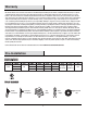
Warranty We warrant the fan motor to be free from defects in workmanship and material present at time of shipment from the factory for a period of lifetime after the date of purchase by the original purchaser. We also warrant that all other fan parts, excluding any glass or acrylic blades, to be free from defects in workmanship and material at the time of shipment from the factory for a period of two years after the date of purchase by the original purchaser.
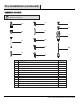
Pre-Installation (continued) HARDWARE INCLUDED NOTE: Hardware shown to actual size unless noted otherwise in the table below.
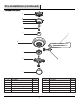
Pre-Installation (continued) PACKAGE CONTENTS A B C D E F H G J K I L Part Description Quantity Part Description Quantity A Mounting bracket (preassembled) 1 G Fan motor assembly 1 B Canopy ring (preassembled) 1 H Blade 5 C Canopy 1 I Blade arm 5 D Canopy bottom cover (preassembled) 1 J Light kit mounting plate 1 E Hanger ball/downrod assembly 1 K Light kit 1 F Coupling cover 1 L Glass shade 3 6
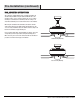
Pre-Installation (continued) DUAL MOUNTING INSTRUCTIONS This ceiling fan is supplied with two types of hanging assemblies: the standard ceiling installation using the downrod with ball and socket mounting, and the "close-to-ceiling" mounting. The "close-to-ceiling" mounting is recommended in rooms with less than 8 ft. ceilings or in areas where additional space is desired from the floor to the fan blades.
Installation MOUNTING OPTIONS NOTE: You may need a longer downrod to maintain proper blade clearance when installing on a steep, sloped ceiling. The maximum angle allowable is 18° away from horizontal. If the canopy (C) touches the hanger ball/downrod assembly (E), then remove the decorative canopy bottom cover (D) and turn the canopy (C) 180° before attaching the canopy (C) to the mounting bracket (A).
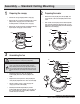
Assembly — Standard Ceiling Mounting 1 2 Preparing the canopy Preparing the motor □ Remove the canopy ring (B) from the canopy (C). □ □ Remove the two non-slotted mounting bracket screws (BB) from the canopy (C), and loosen the slotted mounting bracket screws (BB) on the canopy (C). Remove the clevis pin (CC) and cotter pin (DD), and loosen the two collar setscrews (GG) from the motor collar.
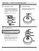
Assembly — Close-to-Ceiling Mounting 1 2 Preparing the canopy □ Remove the mounting bracket (A) from the canopy (C) by loosening the four canopy mounting bracket screws (BB) on the top of the canopy (C). Remove the two non-slotted canopy mounting bracket screws (BB) and loosen the slotted canopy mounting bracket screws (BB). □ Remove the canopy bottom cover (D) from the canopy (C).
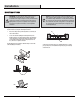
Assembly — Hanging the Fan 4 Attaching the fan to the electrical box WARNING: To reduce the risk of fire, electric shock or other personal injury, mount the fan only to an outlet box or supporting system marked acceptable for fan support and use the mounting screws provided with the outlet box. □ Pass the 120-volt supply wires through the center hole in the mounting bracket (A).
Assembly — Hanging the Fan (continued) RR WARNING: To avoid possible electrical shock, be sure electricity is turned off at the main fuse box before wiring. SS WARNING: Check to see that all connections are tight, including ground, and that no bare wire is visible at the wire nuts (except for the ground wire). Follow the steps below to connect the fan to your household wiring. Use the plastic wire nuts (AA) with your fan. Secure the plastic wire nuts (AA) with electrical tape.
Assembly — Hanging the Fan (continued) 7a 7b Standard ceiling mounting WARNING: Locking slots of the canopy (C) are provided only as an aid to mounting. Do not leave the fan assembly unattended until all four canopy screws (BB) are engaged and firmly tightened. WARNING: Make sure the tab on the mounting bracket (A) properly sits in the groove in the hanger ball (E) before attaching the canopy (C) to the mounting bracket (A) by turning the canopy (C) until it drops into place.
Assembly — Attaching the Fan Blades 8 Attaching the blades to the blade arms WARNING: Failure to properly seat the blades (H) on the blade arms (I) and engage in the spring locking mechanism (AAA) could result in the fan blades (H) loosening and possibly falling. I To install the blade to the blade arm: □ □ Hold the blade (H) with hands close to the blade arm (I), align the key-slot holes (YY) with the blade arm posts (ZZ) and press the blade down firmly.
Assembly — Attaching the Fan Blades 9 Fastening the blade assemblies to the motor WARNING: To reduce the risk of personal injury, do not bend the blade arms (I) while installing, balancing the blades (H), or cleaning the fan. Do no insert foreign objects between rotating fan blades (H). □ Fasten the blade assemblies to the fan motor assembly (G) by lining up the slots of the motor (BBB) with the tabs (CCC) on the blade arms (I).
Assembly — Installing the Light Kit 10 Attaching the light kit mounting plate to the mounting ring 11 CAUTION: Before starting installation, disconnect the power by turning off the circuit breaker or removing the fuse at the fuse box. Turning power off using the fan switch is not sufficient to prevent electric shock. □ Remove one of the three light kit mounting plate screws (JJ) from the mounting ring (DDD) and loosen the other two screws (JJ).
Assembly — Installing the Light Kit (continued) 12 Installing the light bulb and glass shade CAUTION: Before starting installation, disconnect the power by turning off the circuit breaker or removing the fuse at the fuse box. Turning power off using the fan switch is not sufficient to prevent electric shock. □ Raise the glass shade (L) up against the light kit (K) and secure the glass shade (L) to the light (K) kit by turning the glass shade (L) clockwise until snug. Do not overtighten.
Operation PULL CHAIN OPERATING INSTRUCTIONS Install two pull chains and fobs (MM) onto the pull chains located in the light kit (K). Turn on the power and check the operation of the fan. The pull chain controls the fan speed as follows: 1 pull - High, 2 pulls - Medium, 3 pulls - Low, and 4 pulls - Off. Speed settings for warm or cool weather depend on factors such as the room size, ceiling height, and number of fans. The light pull chain controls the light kit: "ON" and "OFF".
Care and Cleaning Do □ Do not Check the support connections, brackets, and blade attachments twice a year. Make sure they are secure. Because of the fan’s natural movement, some connections may become loose over time. It is not necessary to remove the fan from the ceiling. □ Clean your fan periodically. Use only a soft brush or lint-free cloth to avoid scratching the finish. The plating is sealed with a lacquer to minimize discoloration or tarnishing.
Troubleshooting (continued) Problem Solution □ Verify that all blades and blade bracket screws are secure (most fan wobble problems are caused by loose parts). Once the fan is properly installed, run the ceiling fan for 10 minutes to let the fan self-adjust. If wobble occurs after running the fan for 10 minutes, verify blade level using the following process: The fan wobbles.
Service Parts AA A GG MM H B C D I BB HH CC II E J JJ DD F K KK EE G Part L FF Description Part LL Description A Mounting bracket (preassembled) AA Plastic wire nut B Canopy ring (preassembled) BB Canopy mounting bracket screw with lock washer C Canopy D Canopy bottom cover (preassembled) CC (preassembled) Clevis pin (preassembled) E Hanger ball/downrod assembly DD Cotter pin (preassembled) F Coupling cover EE Setscrew (preassembled) G Fan motor assembly FF Cro
Questions, problems, missing parts? Before returning to the store, call Home Decorators Collection Customer Service 8 a.m. - 6 p.m., EST, Monday-Friday 1-800-986-3460 HOMEDEPOT.COM/HOMEDECORATORS Retain this manual for future use.