Item #1005 710 274 1005 710 280 Model #YG922B-MBK YG922B-MWH USE AND CARE GUIDE METARIE II 24 IN. CEILING FAN Questions, problems, missing parts? Before returning to the store, call Hampton Bay Customer Service 8 a.m. - 7 p.m., EST, Monday-Friday, 9 a.m. - 6 p.m., EST Saturday 1-855-HD-HAMPTON HAMPTONBAY.COM Visual instruction of how to install this fan: Visit www.homedepot.
Table of Contents Table of Contents . . . . . . . . . . . . . . . . . . . . . . . . . . . . . . . . . . 2 Operation . . . . . . . . . . . . . . . . . . . . . . . . . . . . . . . . . . . . . . . . 16 Pull Chain Operating Instructions . . . . . . . . . . . . . . . . . . . . 16 Reverse Switch Operating Instruction . . . . . . . . . . . . . . . . . 16 Safety Information . . . . . . . . . . . . . . . . . . . . . . . . . . . . . . . . . . 3 Warranty . . . . . . . . . . . . . . . . . . . . . . . . . . . . . . .
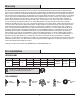
Safety Information However, there is no guarantee that interference will not occur in a particular installation. If this equipment does cause harmful interference to radio or television reception, which can be determined by turning the equipment off and on, the user is encouraged to try to correct the interference by one or more of the following measures: - Reorient or relocate the receiving antenna. - Increase the separation between the equipment and receiver.
Warranty The manufacturer warrants the fan motor to be free from defects in workmanship and material present at time of shipment from the factory for a period of lifetime after the date of purchase by the original purchaser. The manufacturer warrants the light kit (excluding any glass), to be free from defects in workmanship and material at the time of shipment from the factory for a period of three years after the date of purchase by the original purchaser.
Pre-Installation (continued) HARDWARE INCLUDED NOTE: Hardware not shown to actual size. Part AA BB CC DD EE FF Description Quantity AA Plastic wire nut 3 BB Blade attachment screw 13 CC Blade attachment nut 13 DD Blade attachment lock washer 13 EE 9 Watt LED bulb 1 FF Pull chain and fob 2 5 HAMPTONBAY.COM Please contact 1-855-HD-HAMPTON for further assistance.
Pre-Installation (continued) PACKAGE CONTENTS A B C D F G E H I J Part Description Quantity Part Description Quantity A Mounting bracket (preassembled) 1 F Blade arm 4 B Canopy 1 G Blade 4 C Canopy bottom cover (preassembled) 1 H Switch housing 1 D Hanger ball/downrod assembly 1 I Light kit 1 E Fan motor assembly 1 J Plastic shade 1 6
Installation MOUNTING OPTIONS NOTE: You may need a longer downrod to maintain proper blade clearance when installing on a steep, sloped ceiling. The maximum angle allowable is 18° away from horizontal. If the canopy (B) touches the hanger ball/downrod assembly (D), remove the decorative canopy bottom cover (C) and turn the canopy (B) 180° before attaching the canopy (B) to the mounting bracket (A).
Assembly 1 2 Preparing the motor Preparing the canopy Remove the canopy bottom cover (C) from the canopy (B) by turning the canopy bottom cover (C) counterclockwise. Remove the cotter pin (HH) and clevis pin (II), and loosen the two collar setscrews (JJ) from the motor collar. Remove the mounting bracket (A) from the canopy (B) by removing the non-slotted canopy mounting screws (GG) from the bottom of the canopy (B) and loosening the slotted canopy mounting screws (GG) a half turn from the screw head.
Assembly — Hanging the Fan 4 Installing the mounting bracket to the electrical box 5 WARNING: To reduce the risk of fire, electric shock or other personal injury, mount the fan only to an outlet box or supporting system marked acceptable for fan support and use the mounting screws provided with the outlet box. Hanging the fan to the mounting bracket WARNING: The tab in the ring must rest in the groove of the hanger ball/downrod assembly (D).
Assembly — Hanging the Fan (continued) 6a Making the electrical connections WARNING: To avoid possible electrical shock, be sure electricity is turned off at the main fuse box before wiring. WARNING: Check to see that all connections are tight, including ground, and that no bare wire is visible at the wire nuts (except for the ground wire). Hot Neutral Black White WARNING: To reduce the risk of fire or electric shock, do not use this fan with any solid-state speed control device.
Assembly — Hanging the Fan (optional) 6b 6c Single Switch Connections Dual Switch Connections On a single switch the fan and light can be turned on or off together. Make wire connections as follows, using the wire nuts (AA). Wall switch not included. On a dual switch the fan and light can be turned on or off separately. Make wire connections as follows, using the wire nuts (AA). Wall switch not included.
Assembly — Hanging the Fan (continued) 7 8 Installing the canopy WARNING: Make sure the tab on the mounting bracket (A) properly sits in the groove in the hanger ball (D) before attaching the canopy (B) to the mounting bracket (A) by turning the canopy housing until it drops into place. Attaching the canopy bottom cover NOTE: Adjust the canopy mounting screws (GG) as necessary until the canopy (B) and canopy bottom cover (C) are snug.
Assembly — Attaching the Fan Blades 9 Attaching the blades to the blade arms 10 Attach the blades (G) to the blade arms (F) using the blade screws (BB) , nuts (CC) , lock washers (DD). Starting a screw into the blade arm and blade, repeat for the other 2 screws, DO NOT tighten too much as the blades (G) may crack. Tighten each screw (BB) securely starting with the center screw (BB). Make sure the blade is straight.
Assembly — Installing the Light Kit Attaching the switch housing to the mounting ring 11 12 Attaching the light kit to the switch housing Remove one of the four light kit mounting screws (OO) from the switch housing (H) and loosen the other three screws (OO). (Do not remove.) CAUTION: Before starting installation, disconnect the power by turning off the circuit breaker or removing the fuse at the fuse box. Turning power off using the fan switch is not sufficient to prevent electric shock.
Assembly — Installing the Light Kit (continued) 13 Installing the light bulbs and plastic shade CAUTION: Before starting installation, disconnect the power by turning off the circuit breaker or removing the fuse at the fuse box. Turning power off using the fan switch is not sufficient to prevent electric shock. Install one 9 watt LED bulbs (EE) (included). Position the notches (QQ) in the outer rim of the plastic shade (J) so they line up with the tabs (RR) on the inside of the rim on the light kit (I).
Operation PULL CHAIN OPERATING INSTRUCTIONS Install the pull chains and fobs (FF) onto the pull chains located in the switch housing (H). Turn on the power and check the operation of the fan. The pull chain controls the fan speed as follows: 1 pull - High, 2 pulls - Medium, 3 pulls - Low, and 4 pulls - Off. Speed settings for warm or cool weather depend on factors such as the room size, ceiling height, and numbers of fans.
Care and Cleaning Do Do not Check the support connections, brackets, and blade attachments twice a year. Make sure they are secure. Because of the fan’s natural movement, some connections may become loose over time. It is not necessary to remove the fan from the ceiling. Use water when cleaning. Water could damage the motor, or the wood, or possibly cause an electrical shock. Apply oil to your fan or motor. The motor has permanently-lubricated sealed ball bearings. Clean your fan periodically.
Troubleshooting (continued) Problem Solution Verify that all blades and blade bracket screws are secure (most fan wobble problems are caused by loose parts). Once the fan is properly installed, run the ceiling fan for 10 minutes to let the fan self-adjust. If wobble occurs after running the fan for 10 minutes, verify blade level using the following process: The fan wobbles.
Service Parts A AA E B FF BB H C CC D F I DD J EE G Description Part Description A Mounting bracket (preassembled) AA Plastic wire nut B Canopy BB Blade attachment screw Part C Canopy bottom cover (preassembled) CC Blade attachment nut D Hanger ball/downrod assembly DD Blade attachment lock washer E Fan motor assembly EE 9 Watt LED bulb F Blade arm FF Pull chain and fob G Blade H Switch housing I Light kit J Plastic shade 19 HAMPTONBAY.
Questions, problems, missing parts? Before returning to the store, call Hampton Bay Customer Service 8 a.m. – 7 p.m., EST, Monday – Friday, 9 a.m. – 6 p.m., EST, Saturday 1-855-HD-HAMPTON HAMPTONBAY.COM Retain this manual for future use.