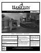
www.hampton-fire.com H15 Direct Vent Gas Fireplace MODELS: H15-NG1 Natural Gas Owners & Installation Manual H15-LP1 Propane WARNING: FOR YOUR SAFETY If the information in these instructions are not followed exactly, a fire or explosion may result What to do if you smell gas: Do not try to light any appliance causing property damage, personal injury or loss of life. Do not touch any electrical switch: do not use any phone in your FOR YOUR SAFETY building.
HAMPTON® Direct Vent Freestanding Gas Stove To the New Owner: Congratulations! You are the owner of a state-of-the-art Hampton® Gas Stove by FPI FIREPLACE PRODUCTS INTERNATIONAL LTD. The H15-1 is a hand crafted appliance and has been designed to provide you with all the warmth and charm of a wood fireplace at the flick of a switch. The model H15-1 has been approved by Warnock Hersey for both safety and efficiency.
TABLE OF CONTENTS MA Code - CO Detector ................................................5 Optional Wall Thermostat ...........................................34 Optional Remote Control ............................................34 Final Check .................................................................34 Wiring Diagrams ..........................................................35 Operating Instructions .................................................37 Lighting Procedure ...........................
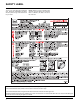
SAFETY LABEL This is a copy of the label that accompanies each Direct Vent Freestanding Gas Stove. We have printed a copy of the contents here for your review. NOTE: Hampton® units are constantly being improved. Check the label on the unit and if there is a difference, the label on the unit is the correct one. For the State of Massachusetts, installation and repair must be done by a plumber or gasfitter licensed in the Commonwealth of Massachusetts.
REQUIREMENTS MA Code - CO Detector (for the State of Massachusetts only) 5.08: Modifications to NFPA-54, Chapter 10 (2) Revise 10.8.
INSTALLATION IMPORTANT MESSAGE SAVE THESE INSTRUCTIONS The Direct Vent Freestanding Gas Stove must be installed in accordance with these instructions. Carefully read all the instructions in this manual first. Consult the building authority having jurisdiction to determine the need for a permit prior to starting the installation. Note: Failure to follow the instructions could cause a malfunction of the heater which could result in death, serious bodily injury, and/or property damage.
INSTALLATION (825mm), a maximum depth of 36" (914mm), and minimum height of 24" (610mm) from top of unit to ceiling. 6) We recommend that you plan your installation on paper using exact measurements for clearances and floor protection before actually installing this appliance. Have a qualified building inspector review your plans before installation. GENERAL SAFETY INFORMATION 1) The appliance installation must conform with local Canadian Electrical Code.
INSTALLATION 4) Remove the nylon hole plug from the control panel. OPTIONAL FAN INSTALLATION LOCATING YOUR GAS STOVE 5) Install the fan speed controller onto the control panel and secure with nut and washer. Connect the red and black wires from the wire harness to speed controller. NOTE: Speed control wires must be in the down position when control panel is in place.
INSTALLATION 9) Remove 2 screws from unit. 12) Slide fan into place and secure with the two screws removed in step 9. 14) Connect fan ground wire to lug nut at base of unit. Lug Nut 10) Place grommet in rear plate through the bottom of the opening as shown below. 13) Connect long black & red wires to thermodisc and secure wires. 15) Before re-attaching the rear access panel, the valve wires and the fan wires need to be connected. Re-connect the red and grey valve wires removed in step 2.
INSTALLATION VENTING INTRODUCTION INSTALLATION PRECAUTIONS SAFETY PRECAUTIONS FOR THE INSTALLER The Horizontal Termination Kit and the Simpson Dura-Vent Direct Vent System Model DV-GS venting systems, in combination with the Direct Vent Freestanding Gas Stoves, H15-NG1, and H15-LP1, have been tested and listed as direct vent heater systems by Warnock Hersey. These venting systems are engineered products that have been designed and tested for use with the H15-NG1, and H15-LP1.
INSTALLATION EXTERIOR VENT TERMINAL LOCATIONS A= B= C= D= Clearance above grade, veranda, porch, deck, or balcony *(min. 12"/30cm) Clearance to window or door that may be opened *(12"/30cm) Clearance to permanently closed window *(min. 12"/30cm) Vertical clearance to ventilated soffit located above the terminal within a horizontal distance of (24"/60cm) from the centerline of the terminal (min. 22"/55cm) check with local code. E= Clearance to unventilated soffit (min.
INSTALLATION 4” X 6-5/8” RIGID PIPE CROSS REFERENCE CHART Components from different Manufacturers may not be mixed. Not All Rigid Pipe components are available directly from FPI.
INSTALLATION 4” x 6-5/8” Rigid Pipe Cross Reference Chart (Cont.) Components from different Manufacturers may not be mixed. Not All Rigid Pipe components are available directly from FPI.
INSTALLATION RIGID PIPE VENTING SYSTEMS Horizontal or Vertical Terminations Alternate Horizontal Termination Caps Vertical Termination Cap Storm Collar Vinyl Siding Standoff (Optional) Flashing Horizontal Termination Cap Ceiling Firestop Wall Thimble Pipe Length Adj.Pipe Length 11" - 14-5/8" 90o Elbow WARNING: Do not combine venting components from different venting systems. 24" Pipe Length However use of the the AstroCapTM and FPI Riser is acceptable with all systems.
INSTALLATION Horizontal Venting with Two (2) 90o Elbows One 90o elbow = Two 45o elbows. Option A) B) C) D) E) F) 1' 2' 3' 4' 5' 6' V Min. Min. Min. Min. Min. Min. H + H1 3' Max. 4' Max. 5' Max. 6' Max. 7' Max. 8' Max. With these options, maximum total pipe length is 30 feet with minimum of 6 feet total vertical and maximum 8 feet total horizontal. Please note minimum 1 foot between 90o elbows is required.
INSTALLATION Vertical Venting with Two (2) 90o Elbows One 90o elbow = Two 45o elbows. Option A) B) C) D) E) V 1' Min. 2' Min. 3' Min. 4' Min. 5' Min. H 4' Max. 5' Max. 6' Max. 7' Max. 8' Max. V + V1 2' Min. 3' Min. 4' Min. 5' Min. 6' Min. With these options, max. total pipe length is 30 feet with min. of 6 feet total vertical and max. 8 feet total horizontal. Please note min. 1 foot between 90o elbows is required.
INSTALLATION VENTING ARRANGEMENTS Horizontal Terminations for All Venting Systems Vertical Terminations Systems for Residential Manufactured and Mobile Homes The shaded areas in the diagram below show all allowable combinations of vertical runs with horizontal terminations. Maximum one 90O elbow (two 45o elbows equal one 90o elbow). The shaded area in the diagram below shows all allowable combinations of straight vertical and offset to vertical runs with vertical terminations. Maximum two 45o elbows.
INSTALLATION VERTICAL TERMINATION WITH CO-LINEAR FLEX SYSTEM THE APPLIANCE MUST NOT BE CONNECTED TO A CHIMNEY FLUE SERVING A SEPARATE SOLID FUEL BURNING APPLIANCE. This appliance is designed to be attached to two 3" (76mm) co-linear aluminium flex running the full length of the chimney. See the Venting Arrangements chart below for minimum and maximum flue lengths. See chart below for minimum distances from roof. Periodically check that the vent is unrestricted.
INSTALLATION DV STOVE HORIZONTAL VENT KIT DV 2 ft. Stove Vent Kit (Part # 946-116) and DV 4 ft. Stove Vent Kit (946-216) includes all the parts needed to install the H15-1 Direct Vent unit with up & out horizontal and vertical vent dimensions. For installations that require longer vertical and/or horizontal vents use the Dura-Vent system as shown in the "Dura-Vent Termination Kit" and "Dura-Vent Venting Components" sections. Qty.
INSTALLATION 9) Secure the 4" dia. flex liner to the 4" adapter with Mill-Pac and 3 of the #8 x 1/2" screws (stainless steel). 10) Slide the decorative Thimble Cover over the pipe sections and secure with 4 screws (#8 x 1-1/2" drill point, black) to the wall. 11) Slide the 90o elbow (crimp end up), the 45o elbow and the 4 ft. pipe section (crimp end up) over the 4" dia. flex liner. 12) Install the spring spacers onto the pipe sections. 13) Secure the 4" dia. flex liner with adapter onto the stove collar.
INSTALLATION RESIDENTIAL AND MANUFACTURED HOMES / MOBILE HOMES MINIMUM HORIZONTAL TERMINATION INSTALLATIONS Planning Your Venting Installation See the "Exterior Vent Terminal Locations" section for requirements. When planning your installation, it will be necessary to select the proper length of vent pipe for your particular requirements. Determine the minimum clearance to combustibles from the rear of the unit to the wall. It is also important to note the wall thickness.
INSTALLATION DURA-VENT TERMINATION KIT Planning Your Dura-Vent Installation There are two basic types of Dura-Vent Direct Vent System installations: horizontal termination and vertical termination. Confirm the maximum horizontal run and maximum vertical rise from the diagrams in the "Rigid Pipe Venting Systems" section. When planning your installation, it will be necessary to select the proper length of vent pipe for your particular requirements.
INSTALLATION You will require the following components with your new Direct Vent Freestanding Gas Stove. Please review your product to make sure you have everything you need. In the event that you are missing any part, contact your dealer. Note: These are the minimum pieces required. Other parts may be required for your particular installation. See above for a list of vent parts.
INSTALLATION c) Before connecting the vent pipe to the vent termination, slide the black decorative wall thimble cover over the vent pipe, then slide the Wall Penetration Heat Shield (Part # 946-202) over the vent pipe. Dia. 3. Diagram 4 7) Install the Backing Plate into the wall penetration heat shield and attach using 4 screws. Dia. 4. d) Slide the appliance and vent assembly towards the wall carefully inserting the vent pipe into the riser vent terminal assembly.
INSTALLATION 7) Ensure vent is vertical and secure the base of the flashing to the roof with roofing rails, slide storm collar over the pipe section and seal with a mastic. 8) Install the vertical termination cap by twist locking it. Diagram 10: The upper half of the flashing is installed under the roofing material and not nailed down until the chimney is installed. This allows for small adjustments.
INSTALLATION CONVERTING CLASS-A METAL CHIMNEY OR MASONRY CHIMNEY TO DIRECT VENT SYSTEM Approved for US Installations Only The use of an existing chimney as an air intake is not covered under the ANSI Z21.88b1999, CSA 2.33b-M99 test methods and the resulting ITS/WHI product certification. The code Authority Having Jurisdiction must be consulted prior to proceeding with this installation method. There are two different types of direct vent conversion systems listed below.
INSTALLATION CATHEDRAL CEILINGS Round Support (RDS) & Square Support (SQS) If your home has a cathedral ceiling (no attic space between the ceiling and the roof), install the chimney and support as follows. 1) Situate the chimney in a convenient location as near as possible to the appliance outlet. Cut and frame a hole in the roof for the support. The sides of this hole must be vertical with 1 1/4" clearance. 2) Place the support in the opening.
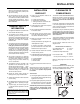
INSTALLATION AERATION ADJUSTMENT GAS PIPE PRESSURE TESTING The air shutter can be adjusted by moving the adjusting wire up or down. The wire is accessed through the bottom. Open the air shutter for a blue flame or close for a yellower flame. The burner aeration is factory set but may need adjusting due to either the local gas supply or altitude.
INSTALLATION CONVERSION KIT# 381-969 FROM NG TO LP THIS CONVERSION MUST BE DONE BY A QUALIFIED GAS FITTER IF IN DOUBT DO NOT DO THIS CONVERSION !! 3) Each Kit contains one LPG Conversion Kit and one DC Sparker Kit. LPG Conversion Kit Contains: Qty. Part # Description 1 904-575 Burner Orifice #55 1 918-590 Label "Converted to Propane" 1 908-528 Red "LPG" label 1 904-529 5/3" Allen Key 1 910-037 LP Injector (Pilot Orifice) 1 918-479 Instruction Sheet DC Sparker Kit Contains: Qty.
INSTALLATION 11) Reassemble the black protection cap (Fig. 6). 22) Attach the DC sparker generator connector to the valve with a screw. 16) Reverse steps 3) to 2). 17) Attach the label "This unit has been converted to LPG" near or on top of the serial # decal. 18) Replace yellow "Natural Gas" label with red "LPG" label. Fig. 6 Installation of the DC Sparker: WARNING! Also check that the pilot and main burner injectors are appropriate for the gas type.
INSTALLATION 25) Attach the Piezo ignition wire to the DC Sparker. 29) Attach the DC sparker generator wires to the DC sparker. 32) Tie up the loose wire with the wire clip. Piezo Ignitor 30) Install the supplied battery into the DC Sparker Box by opening the battery compartment. 26) Insert both the ground wire and the DC sparker generator wire through the hole of the DC spark heat shield. NOTE: The battery in the DC Sparker Box will need to be replaced annually.
INSTALLATION LOG SET INSTALLATION Read the instructions below carefully and refer to the diagrams. If the logs are broken do not use the unit until they are replaced. Broken logs can interfere with the pilot operation. 6) Place the rear log on the 2 rear log locating pins on the rear of the burner with the flat side to the back.
INSTALLATION 8) Take the embers and place on the burner in the space between the 2 front logs, ensure not to cover any burner ports. Do not put embers on the burner in the area between the front logs and the rear log. See photo below. 9) Place the center cross log on the locating pin in the top of the rear log and position as shown below. Logs must be oriented as shown below. Separate platinum embers and place at the front of the burner in and around where the embers are placed.
INSTALLATION OPTIONAL WALL THERMOSTAT A wall thermostat may be installed if desired. Connect the wires as per the wiring diagrams. Note that the wires are connected to the "TH" on the gas valve. Use table below to determine the maximum wire length: OPTIONAL REMOTE CONTROL Use the Hampton® Remote Control Kit approved for this unit. Use of other systems may void your warranty. The remote control kit comes with a hand held transmitter, a receiver and a wall mounting plate.
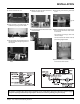
INSTALLATION WIRING DIAGRAMS If any of the original wires as supplied with the appliance must be replaced, it must be replaced with CSA type SEW (200oC) or its equivalent. Caution: Ensure that the wires do not touch any hot surfaces and are away from sharp edges. This heater does not require a 120V A.C. supply for operation. In case of a power failure, the burner switch and the optional remote control/ thermostat will continue to operate. However, a 120V A.C.
INSTALLATION For PROPANE Units and Units Equipped with DC Spark Boxes* *For installation of the DC Spark Box refer to the LP Conversion instructions in this manual.
OPERATING INSTRUCTIONS OPERATING INSTRUCTIONS IMPORTANT: Gas on/off knob cannot be turned from "PILOT" to "OFF" unless it is partially depressed. 1) Read and understand these instructions before operating this appliance. 1) Turn stove OFF using the Burner "ON/OFF" switch remote or thermostat. Switches are located at the top right hand corner (rear) of the stove. 2) Check to see that all wiring is correct and enclosed to prevent possible shock.
OPERATING INSTRUCTIONS COPY OF THE LIGHTING PLATE INSTRUCTIONS FOR YOUR SAFETY READ BEFORE LIGHTING This appliance must be installed in accordance with local codes, if any; if none, follow the National Fuel Gas Code, ANSI Z223.1/ NFPA 54, or Natural Gas and Propane Installation Codes, CSA B149.1. (Australia: AS5601-2004, New Zealand: NZS 5261) WARNING: If you do not follow these instructions exactly, a fire or explosion may result causing property damage, personal injury or loss of life.
MAINTENANCE NORMAL OPERATING SOUNDS OF GAS APPLIANCES It is possible that you will hear some sounds from your gas appliance. This is perfectly normal due to the fact that there are various gauges and types of steel used within your appliance. Listed below are some examples. All are normal operating sounds and should not be considered as defects in your appliance. Blower: Hampton® gas appliances use high tech blowers to push heated air farther into the room.
MAINTENANCE GENERAL VENT MAINTENANCE Conduct an inspection of the venting system semi-annually. Recommended areas to inspect as follows: 1) Check the Venting System for corrosion in areas that are exposed to the elements. These will appear as rust spots or streaks, and in extreme cases, holes. These components should be replaced immediately.
MAINTENANCE REMOVING VALVE If your valve requires maintenance or replacement, use the following instructions: 9) Remove burner by removing the 2 screws on each side, slide the burner to the left and then lift the burner tray out. 12) To remove the valve, remove the 4 screws (2 per bracket) that hold the valve to the valve bracket assembly. 13) To replace the burner tray assembly, simply reverse these instructions. Note: Always close off the gas supply before removing the valve.
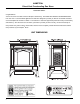
PARTS LIST MAIN ASSEMBLY Part # Description 1) 2) 3) 942-601** 942-621** 942-611** Casting - Top Casting - Side & Leg Casting - Front 6) 7) 8) 9) 10) 11) 12) 13) 770-066F W260280 770-067F 942-117 W260260 945F W842051 W260108 Top Relief Plate Top Relief Plate Gasket Plate Insulation Holder Top Relief Frame Top Relief Frame Gasket Dura-Vent Collar Gasket for Flue Adaptor Gasket for Inner Flue 14) 15) 16) 17) * 380-024 380-023 910-142 Rear Bracket Fan Deflector - Right Fan Deflector - Left Thermodisc S
PARTS LIST BURNER & LOG ASSEMBLY Part # 60) 63) 64) 65) 66) 67) 68) 69) 73) 74) 75) 80) 88) 89) 90) Description 380-574/P 910-478 904-434 910-190 908-672 490-061 936-170 910-038 910-039 380-013 W840470 380-019 380-032 380-033 380-930 380-505 380-015 * * Valve/Pilot Assembly - S.I.T. - NG Valve S.I.T. - NG/LPG #47 Orifice - NG Piezo Ignitor & Nut Control Panel Decal Switch Plate Orifice Gasket Pilot Assy-S.I.T. - 3 flame - NG Pilot Assy-S.I.T.
NOTES ___________________________________________________ ___________________________________________________ ___________________________________________________ ___________________________________________________ ___________________________________________________ ___________________________________________________ ___________________________________________________ ___________________________________________________ ___________________________________________________ ______________________________________
NOTES ___________________________________________________ ___________________________________________________ ___________________________________________________ ___________________________________________________ ___________________________________________________ ___________________________________________________ ___________________________________________________ ___________________________________________________ ___________________________________________________ ______________________________________
NOTES ___________________________________________________ ___________________________________________________ ___________________________________________________ ___________________________________________________ ___________________________________________________ ___________________________________________________ ___________________________________________________ ___________________________________________________ ___________________________________________________ _____________________________________
WARRANTY Hampton Fireplace Products are designed with reliability and simplicity in mind. In addition, our internal Quality Assurance Team carefully inspects each unit thoroughly before it leaves our facility. FPI Fireplace Products International Ltd. is pleased to extend this limited lifetime warranty to the original purchaser of a Hampton Product. This warranty is not transferable.
Hampton® fireplace products are designed with reliability and simplicity in mind. In addition, our internal Quality Assurance Team carefully inspects each unit thoroughly before it leaves our door. FPI Fireplace Products International Ltd. is pleased to extend this Limited Lifetime Warranty to the original purchaser of a Hampton® Product. See the inside back cover for details. Register your Hampton® online at http://www.hampton-fire.