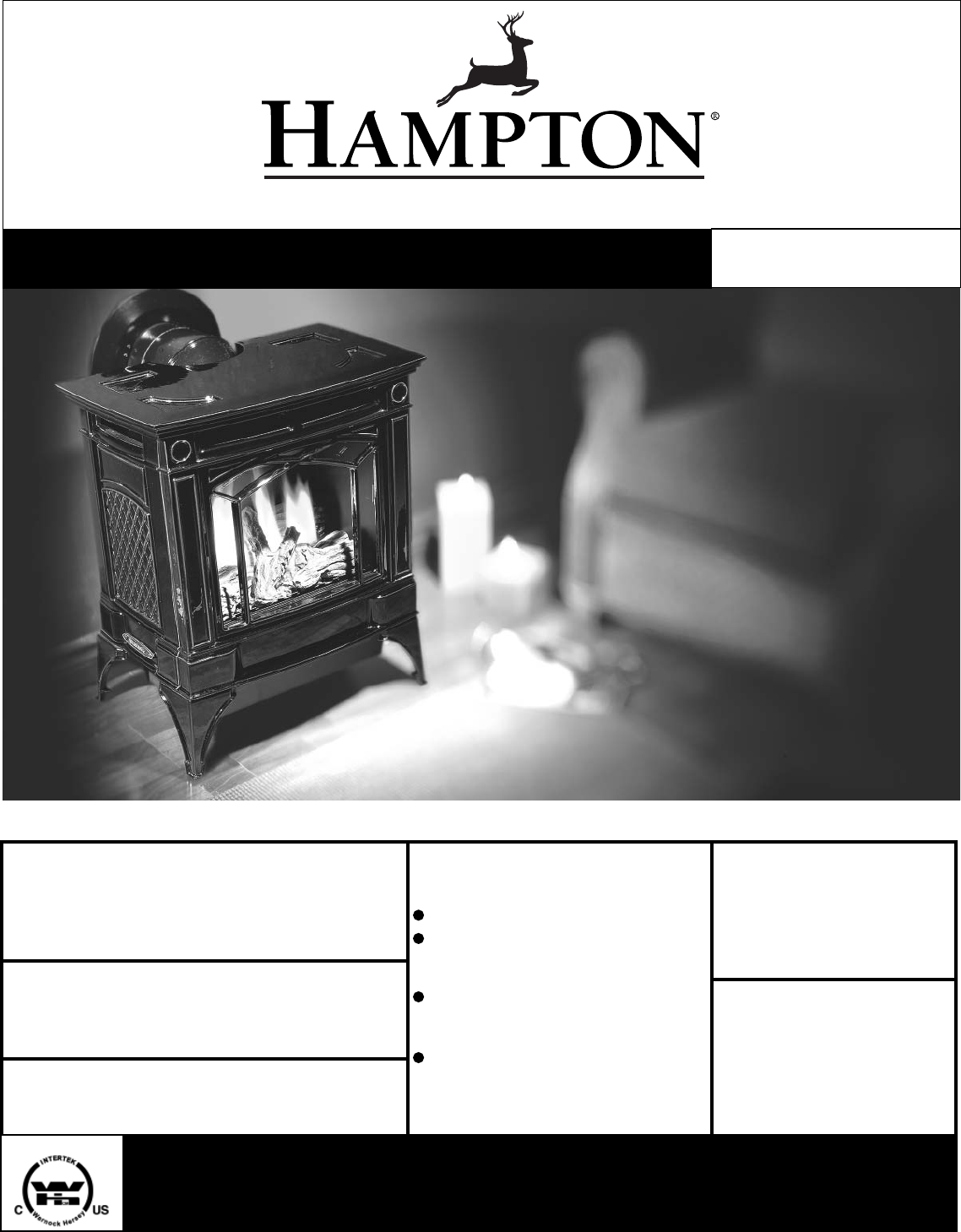
www.hampton-fire.com H25 Direct Vent Gas Fireplace MODELS: H25-NG1 Natural Gas Owners & Installation Manual H25-LP1 Propane FOR YOUR SAFETY WARNING: If the information in these instructions are not followed exactly, a fire or explosion may result What to do if you smell gas: Do not try to light any appliance causing property damage, personal injury or loss Do not touch any electrical switch: of life. do not use any phone in your building.
HAMPTON® Direct Vent Freestanding Gas Stove To the New Owner: Congratulations! You are the owner of a state-of-the-art Hampton® Gas Stove by FPI FIREPLACE PRODUCTS INTERNATIONAL LTD. The H25 is a hand crafted appliance and has been designed to provide you with all the warmth and charm of a wood fireplace at the flick of a switch. The model H25 has been approved by Warnock Hersey for both safety and efficiency.
TABLE OF CONTENTS SAFETY LABEL Safety Label ..................................................................4 REQUIREMENTS Log Set Installation ......................................................32 Decorative Door Grill Installation .................................34 Wall Thermostat .........................................................34 Remote Control ..........................................................34 Final Check .................................................................
SAFETY LABEL This is a copy of the label that accompanies each Direct Vent Freestanding Gas Stove. We have printed a copy of the contents here for your review. NOTE: Hampton® units are constantly being improved. Check the label on the unit and if there is a difference, the label on the unit is the correct one. COPY OF SAFETY LABEL FOR H25-NG1 & H25-LP1 For the State of Massachusetts, installation and repair must be done by a plumber or gasfitter licensed in the Commonwealth of Massachusetts.
REQUIREMENTS MA Code - CO Detector (for the State of Massachusetts only) 5.08: Modifications to NFPA-54, Chapter 10 (2) Revise 10.8.
INSTALLATION IMPORTANT MESSAGE SAVE THESE INSTRUCTIONS The Direct Vent Freestanding Gas Stove must be installed in accordance with these instructions. Carefully read all the instructions in this manual first. Consult the building authority having jurisdiction to determine the need for a permit prior to starting the installation. Note: Failure to follow the instructions could cause a malfunction of the heater which could result in death, serious bodily injury, and/or property damage.
INSTALLATION Thermostat. Some areas may have further requirements, check local codes before installation. 5) This appliance is Listed for Alcove installations, maintain minimum Alcove clearances as follows, minimum width of 34-3/4" (882mm), a maximum depth of 36" (914mm), and minimum ceiling height of 51" (1295mm) from floor to ceiling. 6) We recommend that you plan your installation on paper using exact measurements for clearances and floor protection before actually installing this appliance.
INSTALLATION LOCATING YOUR GAS STOVE When selecting a location for your stove, ensure that the clearances listed above are met as well as ensuring that there is adequate accessibility for servicing and proper operation. OPTIONAL FAN INSTALLATION 4) Remove the nylon hole plug from the control panel. Fan Kit Contains: Qty.
INSTALLATION 9) Place the blower close to the base of the unit and feed the long red and black wires through the opening of the base of the unit and connect them to the thermodisc. 12) Before re-attaching the rear access panel, the valve wires and the fan wires need to be connected. Re-connect the red and grey valve wires. Connect the fan wires. 10) Feed the short red and black wires through the small hole at the base of the unit.
INSTALLATION VENTING INTRODUCTION INSTALLATION PRECAUTIONS SAFETY PRECAUTIONS FOR THE INSTALLER The Horizontal Termination Kit and the Simpson Dura-Vent Direct Vent System Model DV-GS venting systems, in combination with the Direct Vent Freestanding Gas Stoves, H25-NG1, and H25-LP1, have been tested and listed as direct vent heater systems by Warnock Hersey. These venting systems are engineered products that have been designed and tested for use with the H25-NG1, and H25-LP1.
INSTALLATION EXTERIOR VENT TERMINAL LOCATIONS A= B= C= D= Clearance above grade, veranda, porch, deck, or balcony *(min. 12"/30cm) Clearance to window or door that may be opened *(12"/30cm) Clearance to permanently closed window *(min. 12"/30cm) Vertical clearance to ventilated soffit located above the terminal within a horizontal distance of (24"/60cm) from the centerline of the terminal (min. 22"/55cm) check with local code. E= Clearance to unventilated soffit (min.
INSTALLATION 4” X 6-5/8” RIGID PIPE CROSS REFERENCE CHART Components from different Manufacturers may not be mixed. Not All Rigid Pipe components are available directly from FPI.
INSTALLATION 4” x 6-5/8” Rigid Pipe Cross Reference Chart (Cont.) Components from different Manufacturers may not be mixed. Not All Rigid Pipe components are available directly from FPI.
INSTALLATION RIGID PIPE VENTING SYSTEMS Horizontal or Vertical Terminations Vertical Termination Cap Alternate Horizontal Termination Caps Storm Collar Vinyl Siding Standoff (Optional) Flashing Horizontal Termination Cap Ceiling Firestop Wall Thimble Pipe Length Adj.Pipe Length 11" - 14-5/8" 90o Elbow WARNING: Do not combine venting components from different venting systems. 24" Pipe Length However use of the the AstroCapTM and FPI Riser is acceptable with all systems.
INSTALLATION VENTING ARRANGEMENTS Horizontal Terminations for All Venting Systems Vertical Terminations Systems for Residential Manufactured and Mobile Homes The shaded areas in the diagram below show all allowable combinations of vertical runs with horizontal terminations. Maximum one 90O elbow (two 45o elbows equal one 90o elbow). The shaded area in the diagram below shows all allowable combinations of straight vertical and offset to vertical runs with vertical terminations. Maximum two 45o elbows.
INSTALLATION Horizontal Venting with Two (2) 90o Elbows One 90o elbow = Two 45o elbows. Option A) B) C) D) E) 2' 3' 4' 5' 6' V Min. Min. Min. Min. Min. H + H1 4' Max. 5' Max. 6' Max. 7' Max. 8' Max. With these options, maximum total pipe length is 30 feet with minimum of 6 feet total vertical and maximum 8 feet total horizontal. Please note minimum 1 foot between 90o elbows is required.
INSTALLATION Vertical Venting with Two (2) 90o Elbows One 90o elbow = Two 45o elbows. Option A) B) C) D) E) V 1' Min. 2' Min. 3' Min. 4' Min. 5' Min. H 4' Max. 5' Max. 6' Max. 7' Max. 8' Max. V + V1 2' Min. 3' Min. 4' Min. 5' Min. 6' Min. With these options, max. total pipe length is 30 feet with min. of 6 feet total vertical and max. 8 feet total horizontal. Please note min. 1 foot between 90o elbows is required.
INSTALLATION VERTICAL TERMINATION WITH CO-LINEAR FLEX SYSTEM THE APPLIANCE MUST NOT BE CONNECTED TO A CHIMNEY FLUE SERVING A SEPARATE SOLID FUEL BURNING APPLIANCE. This appliance is designed to be attached to two 3" (76mm) co-linear aluminium flex running the full length of the chimney. See the Venting Arrangements chart below for minimum and maximum flue lengths. See chart below for minimum distances from roof. Periodically check that the vent is unrestricted.
INSTALLATION DV STOVE HORIZONTAL VENT KIT DV 2 ft. Stove Vent Kit (Part # 946-116) and DV 4 ft. Stove Vent Kit (946-216) includes all the parts needed to install the H25 Direct Vent unit with minimum horizontal and vertical vent dimensions. For installations that require longer vertical and/or horizontal vents use the Dura-Vent system as shown in the "Dura-Vent Termination Kit" and "Dura-Vent Venting Components" sections. Qty.
INSTALLATION 9) Secure the 4" dia. flex liner to the 4" adapter with Mill-Pac and 3 of the #8 x 1/2" screws (stainless steel). 10) Slide the decorative Thimble Cover over the pipe sections and secure with 4 screws (#8 x 1-1/2" drill point, black) to the wall. 11) Slide the 90o elbow (crimp end up), the 45o elbow and the 4 ft. pipe section (crimp end up) over the 4" dia. flex liner. 12) Install the spring spacers onto the pipe sections. 13) Secure the 4" dia. flex liner with adapter onto the stove collar.
INSTALLATION RESIDENTIAL AND MANUFACTURED HOMES / MOBILE HOMES MINIMUM HORIZONTAL TERMINATION INSTALLATIONS Planning Your venting Installation See the "Exterior Vent Terminatal Locations" section for requirements. The H25 is approved for a minimum horizontal termination with the FPI Riser Vent Kit. See the diagram for minimum and maximum pipe lengths. You will require the following components with your new Hampton® Rear Vent Direct Vent Freestanding Gas Stove.
INSTALLATION DURA-VENT TERMINATION KIT Planning Your Dura-Vent Installation There are two basic types of Dura-Vent Direct Vent System installations: horizontal termination and vertical termination. Confirm the maximum horizontal run and maximum vertical rise from the diagrams in the "Venting Arrangment" section. When planning your installation, it will be necessary to select the proper length of vent pipe for your particular requirements.
INSTALLATION You will require the following components with your new Direct Vent Freestanding Gas Stove. Please review your product to make sure you have everything you need. In the event that you are missing any part, contact your dealer. Note: These are the minimum pieces required. Other parts may be required for your particular installation. See above for a list of vent parts.
INSTALLATION c) Before connecting the vent pipe to the vent termination, slide the black decorative wall thimble cover over the vent pipe, then slide the Wall Penetration Heat Shield (Part # 946-202) over the vent pipe. Dia. 3. Diagram 4 7) Install the Backing Plate into the wall penetration heat shield and attach using 4 screws. Dia. 4. d) Slide the appliance and vent assembly towards the wall carefully inserting the vent pipe into the riser vent terminal assembly.
INSTALLATION 7) Ensure vent is vertical and secure the base of the flashing to the roof with roofing rails, slide storm collar over the pipe section and seal with a mastic. 8) Install the vertical termination cap by twist locking it. Diagram 8 3) To install the Round Support Box/Wall Thimble in a flat ceiling, cut a 10 inch square hole in the ceiling centred on the hole drilled in Step 2. Frame the hole as shown in diagram 9.
INSTALLATION CONVERTING CLASSA METAL CHIMNEY OR MASONRY CHIMNEY TO DIRECT VENT SYSTEM Approved for US Installations Only The use of an existing chimney as an air intake is not covered under the ANSI Z21.88b1999, CSA 2.33b-M99 test methods and the resulting ITS/WHI product certification. The code Authority Having Jurisdiction must be consulted prior to proceeding with this installation method. There are two different types of direct vent conversion systems listed below.
INSTALLATION 7) Ensure vent is vertical and secure the base of the flashing to the roof with roofing rails, slide storm collar over the pipe section and seal with a mastic. Note: If you are using a 6" square support you may find it difficult to screw it in place because it is fairly small inside. Since some municipalities have additional local codes it is always best to consult with your local authorities and the CAN/CGA B149 installation codes. 8) Install the vertical termination cap by twist locking it.
INSTALLATION To adjust the aeration: use the allen key to turn the turning gear which will adjust the air shutter. Open the air shutter for a blue flame or close it for a more yellow flame. This adjustment is performed by a qualified installer. The factory setting should be sufficient for most installations.
INSTALLATION CONVERSION KIT #434-969 FROM NG TO LP THIS CONVERSION MUST BE DONE BY A QUALIFIED GAS FITTER IF IN DOUBT DO NOT DO THIS CONVERSION !! d) Remove the 2 screws holding the Burner Assembly to the firebox base. Push the Burner Assembly to the left and lift out. Each Kit contains one LPG Conversion Kit and one DC Sparker Kit. LPG Conversion Kit Contains: Qty.
INSTALLATION 7) Turn control knob to the “OFF” position. 8) Remove the black protection cap by hand from the high-low knob (Fig.1). 12) Using the Allen wrench as shown in Fig.4, rotate the screw clockwise until snug, do not overtighten. 15) Reverse step 2. 16) Attach the label "This unit has been converted to LPG" near or on top of the serial # decal. 17) Replace yellow "NG" label with red "LPG" label. 18) Check for gas leaks. 19) Check inlet and outlet pressures. 20) Check operation of flame control.
INSTALLATION Installation of the DC Sparker for the H25-1 Unit Only: 1) 5) Remove the stove’s rear panel by unscrewing the two screws. 11) Attach the ground wire to the DC spark mounting bracket. Remove the control panel by unscrewing the 2 screws. 12) Attach the DC sparker generator wires to the DC sparker. 2) 6) Attach the ground wire to the grounding stud. 7) Attach the ground wire to the grounding stud. First, remove the Piezo Ignition Wire from the Piezo Ignitor.
INSTALLATION LOG SET INSTALLATION Read the instructions below carefully and refer to the diagrams. If the logs are broken do not use the unit until they are replaced. Broken logs can interfere with the pilot operation. 5) Place the 2 front logs on the front log locating pins. Ensure the back of both logs rest against the tabs.
INSTALLATION 6) Take the embers and place on the burner in the space between the 2 front logs. Do not put embers on the burner in the area between the front logs and the rear log. See photo below. 8) Test fire to ensure proper light off (make sure flame flows smoothly from one end of burner to the other). If there is any flame hesitation, check that area for any blockage of the burner ports. Separate platinum embers and place at the front of the burner in and around where the embers are placed.
INSTALLATION DECORATIVE DOOR GRILL INSTALLATION 1) Turn the Grill Latches on the Rear of the Door Grill as per the photo below. WALL THERMOSTAT A wall thermostat may be installed if desired. Connect the wires as per the wiring diagrams. Note that the wires are connected to the "TH" on the gas valve. Use table below to determine the maximum wire length: Note: Preferable if the thermostat is installed on an interior wall.
INSTALLATION FINAL CHECK Before leaving this unit with the customer, the installer must ensure that the appliance is firing correctly. This includes: 2) If required, adjusting the primary air to ensure that the flame does not carbon. First allow the unit to burn for 15 min. to stabilize. CAUTION Any alteration to the product that causes sooting or carboning that results in damage to the exterior facia is not the responsibility of the manufacturer. 3) Check for proper draft.
INSTALLATION For PROPANE Units and Units Equipped with DC Spark Boxes* *For installation of the DC Spark Box refer to the LP Conversion instructions in this manual. WARNING: Electrical Grounding Instructions This appliance is equipped with a three pronged (grounding) plug for your protection against shock hazard and should be plugged directly into a properly grounded three-prong receptacle. Do not cut or remove the grounding prong from this plug.
OPERATING INSTRUCTIONS OPERATING INSTRUCTIONS located at the top right hand corner (rear) of the stove. DO NOT ATTEMPT TO CLEAN THE GLASS WHILE IT IS STILL HOT! 1) Read and understand these instructions before operating this appliance. Note: When the glass is cold and the appliance is lit, it may cause condensation and fog the glass. This condensation is normal and will disappear in a few minutes as the glass heats up. 2) Check to see that all wiring is correct and enclosed to prevent possible shock.
OPERATING INSTRUCTIONS COPY OF THE LIGHTING PLATE INSTRUCTIONS FOR YOUR SAFETY READ BEFORE LIGHTING This appliance must be installed in accordance with local codes, if any; if none, follow the National Fuel Gas Code, ANSI Z223.1/ NFPA 54, or Natural Gas and Propane Installation Codes, CSA B149.1. (Australia: AS5601-2004, New Zealand: NZS 5261) WARNING: If you do not follow these instructions exactly, a fire or explosion may result causing property damage, personal injury or loss of life.
MAINTENANCE NORMAL OPERATING SOUNDS OF GAS APPLIANCES It is possible that you will hear some sounds from your gas appliance. This is perfectly normal due to the fact that there are various gauges and types of steel used within your appliance. Listed below are some examples. All are normal operating sounds and should not be considered as defects in your appliance. Blower: Hampton® gas appliances use high tech blowers to push heated air farther into the room.
MAINTENANCE GENERAL VENT MAINTENANCE 1) Lift off the Cast Top. FAN MAINTENANCE If your fan requires maintenance or replacement, access to the fan is through the rear access panel on the back of the unit. NOTE: the unit MUST NOT be operated without the fan access panel securely in place and correctly sealed. Conduct an inspection of the venting system semi-annually. Recommended areas to inspect as follows: 1) Check the Venting System for corrosion in areas that are exposed to the elements.
MAINTENANCE 3) Unclip the black and white wires from the fan motor. 4) Remove the 2 bolts holding the fan to the rear base. Disconnect the green ground wire from the right side of the fan as soon as you can reach it. 6) Disconnect piezo wire. 7) Lift off the Cast Top and lift out the front door. 12) To remove the valve, remove the 4 screws (2 per bracket) that hold the valve to the valve bracket assembly. 8) Carefully remove the logs and embers.
PARTS LIST MAIN ASSEMBLY Part # Description 1) 3) 4) 5) 6) 7) 8) 942-421** 942-381** 942-431** 942-441** 350-921** 942-461** 260350 9) 290-015 Casting - Top Casting - Leg Casting - Side Casting - Front Casting - Front Deco Grill Casting - Skirt Gasket for Rear Relief Plate Rear Relief Plate 18) 19) 22) 23) 24) 350-524 350-002 350-006 41225 940-327/P 350-007 Front Door Assembly Door Support Door Frame Gasket - Tadpole Replacement Glass Glass Bracket 30) 38) 43) 948-219 * 948-255 918-517 Hampton®
PARTS LIST BURNER & LOG ASSEMBLY 60) 63) 64) 65) 66) 67) 68) 69) 70) 71) 73) 74) 75) Part # Description 350-574/P Valve Assembly S.I.T. - Natural Gas 910-478 Valve S.I.T. - Natural Gas / Propane 904-430 #42 Orifice - N.G. 910-190 Piezo Ignitor & Nut 908-672 Control Panel Decal 490-061 Switch Plate 936-170 Orifice Gasket 910-038 Pilot Assy-S.I.T.-3 flame-NG 66 910-039 Pilot Assy-S.I.T.
NOTES ___________________________________________________ ___________________________________________________ ___________________________________________________ ___________________________________________________ ___________________________________________________ ___________________________________________________ ___________________________________________________ ___________________________________________________ ___________________________________________________ ______________________________________
NOTES ___________________________________________________ ___________________________________________________ ___________________________________________________ ___________________________________________________ ___________________________________________________ ___________________________________________________ ___________________________________________________ ___________________________________________________ ___________________________________________________ ______________________________________
NOTES ___________________________________________________ ___________________________________________________ ___________________________________________________ ___________________________________________________ ___________________________________________________ ___________________________________________________ ___________________________________________________ ___________________________________________________ ___________________________________________________ ______________________________________
WARRANTY Hampton Fireplace Products are designed with reliability and simplicity in mind. In addition, our internal Quality Assurance Team carefully inspects each unit thoroughly before it leaves our facility. FPI Fireplace Products International Ltd. is pleased to extend this limited lifetime warranty to the original purchaser of a Hampton Product. This warranty is not transferable.
Hampton® fireplace products are designed with reliability and simplicity in mind. In addition, our internal Quality Assurance Team carefully inspects each unit thoroughly before it leaves our door. FPI Fireplace Products International Ltd. is pleased to extend this Limited Lifetime Warranty to the original purchaser of a Hampton® Product. See the inside back cover for details. Register your Hampton® online at http://www.hampton-fire.