
User's Manual


User Manual (HB-USP-GT1L-W)
- 6 -
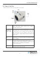
2.1.1 Name of Each Part
Name and function of each part of this product are as follows.
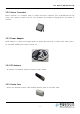
Power terminal○ This is power input terminal to operate the main body of
sensor node. Power adaptor provided upon purchase is
connected to this terminal.
Sensor ○
connection part
(CH1 ~ CH4)
This part is connected to the analog sensor. It can receive input
from voltage sensor of DC0~5V, current sensor of DC 4~20mA
or resistive sensor. It has 4 channels, and each channel has 4
pins. Among them, 2 pins are connected to sensor output and
2 pins are used to supply voltage of DC5V for sensors that
require power.
Communication ○
port
This port is used for RS-485, a representative method of serial
communication. It is used for setting upon shipment. Default
value is 57,600bps.
LEDs ○ This product has 3 LEDs.
- LED #1: Turned ON when wireless module is normal
- LED #2: Turned ON when connecting to nearby sink node
(GT2-W) module and turned OFF once connected
- LED #3: No function
Antenna○ This helical communication antenna is connected to the internal
RF module. Antenna gain is 2.85 dBi.