
Installation Manual
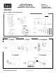


Part Number 3080006.001, Rev. D ©2012, HES, Inc. 8
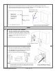
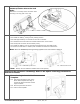
The lock has three LEDs. They support an optical scheme with red, yellow and green. The indication scheme is
described by the figures below:
Fig. Lock Normal operation LED indication
NOTE 1: When the lock mechanism is blocked (lock jammed) the knob must be turned to release it.
NOTE 2: The “Error in lock” indication is also shown instead of the POST flashes if the battery is not accepted as new after a
power-on-reset.
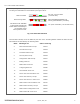
17b. Lock maintenance LED indication
Some special LED indication schemes are used during lock maintenance actions:
Fig. Lock Normal operation LED indication
Access denied,
EAC offline
Three red flashes (.5
s each)
Access granted,
EAC offline or online
One
red
flash
(1 second)
One green flash (1 second)
Access denied,
EAC online
Lock mechanism is
blocked when closing
1)
Continuous red flashes
(
.125
s
econds
every 1 second)
Card read
(configurable)
One yellow flash (.25 second)
Error in lock,
maintenance required
2)
Ten red flashes (.125
seconds each)
repeated if lock can
’
t close
Battery reached end
of life, lock disabled
Continuous red flashes
flashes
(.
25 seconds every 5 seconds)
Time to replace the
battery
Continuous yellow flashes
(.25 seconds every 5 seconds)
Enter configuration
mode
Five yellow flashes
(.125
seconds each)
17 LED Indications
17a. Lock normal operation LED indication