
User's Manual
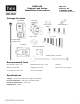

Part Number 3085006.001, Rev. A 5
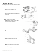
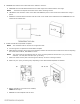
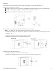
2. TRANSFER the location of the inside wall of the cabinet to the door.
a. MEASURE the horizontal distance between the inside edge of the cabinet and the door edge.
NOTE: The drawn line depicts the location of the strike mounting surface.
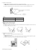
b. LOCATE the lock centerline notch on the latch and MARK this point on the inside of the cabinet door using a
pencil.
c. DRAW the horizontal latch centerline from this mark on the inside of the cabinet door and TRANSFER it to the
outside of the cabinet door.
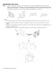
3.
PLACE and USE the Lock/Reader Template.
NOTE: The orientation will be reversed for a right hand door.
a. CUT through line to separate the Strike Plate Template.
b. PEEL OFF the protective layer of the Lock Template, ALIGN it to both the latch centerline and the line depicting
the inside wall of cabinet, and PRESS to secure.
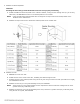
NOTE: Two of the holes in the following step are 3/16” [4.76 mm] diameter and two are 1/2” [12.70 mm]
diameter. The two pilot holes are 1/16” [1.59 mm].
c. DRILL four holes and two pilot holes through the cabinet, as shown in the figure below.
d. DRILL only one 3/16” [4.76 mm] hole, depending on the desired Antenna/Reader orientation.
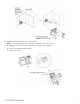
e.
IF the optional key override will be installed,
THEN GO TO Step 5.
f. REMOVE the lock template from the door.