
User's Manual

Part Number 3085006.001, Rev. A 7
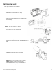
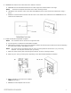
7. INSTALL the Antenna/Reader.
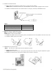
CAUTION
Pinching the wires may prevent the Reader and Lock from properly functioning.
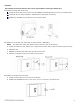
a. PLACE and HOLD the antenna/reader to the outside of cabinet, routing the wire through the 1/2” [12.70 mm]
offset hole, and ENSURE the knob is in the locked position in the vertical.
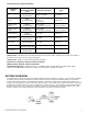
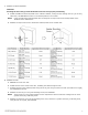
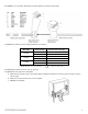
NOTE: Using the table below will help determine the length of the top mount screw needed, based on the
thickness of the cabinet door.
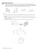
b. INSTALL the top mount screw to attach the antenna/reader to the outside case.
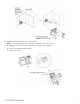
8. INSTALL the lock.
a. REMOVE the cover from lock.
b. PLACE the lock on the inside of the door, threading the cable through the lock.
c. ATTACH the lock to the antenna/reader using two 8-32 [4.00 mm] lock mount screws (see Table 2 for length),
and TIGHTEN the screws.
d. INSTALL the two #6 [3.5 mm] self-threading screws, and TIGHTEN.
NOTE: The third #6 [3.5 mm] self-threading screw is important to achieve maximum holding force for doors
greater than 5/8” [15.88 mm] thick.
e. INSTALL the third #6 [3.5 mm] self-threading screw only if the door is greater than 5/8” [15.88 mm] thick,
using the lock as a guide, and TIGHTEN.