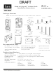
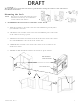
DRAFT HES, Inc. Phoenix, AZ 1.800.626.7590 ® K100-622 Aperio Cabinet Lock Installation Instructions www.hesinnovations.com Package Contents NOTE: The wireless hub and hub bracket are included with the K100-622H model. Template Reader Strike Plate Key Override Paddle In [mm] Screws 2-56 x 7/16” 6 x 1/2” [M1.4 x 0.3 x 11.11 mm] [3.50 mm x 12 mm] 2X 5X 6-32 x 5/16” 2-56 x 1-1/4” [3.5 mm x 7.94 mm] [M1.4 x 0.3 x 31.50 mm] 3X 1X Hub Bracket 8-32 x 5/16” [4.00 mm x 7.
System Overview DRAFT The K100-622 series wireless cabinet lock provides access control to a cabinet or drawer without the complexity and expense of running wires to the cabinet or drawer. The K100-622 series lock connects to an access control through a communication hub (included with the K100-622H). The communication hub connects to the access control system with Wiegand wiring typical of a Wiegand Reader.
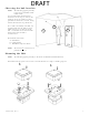
DRAFT Choosing the hub location NOTE: The following applies primarily to the K100-622H Model with included hub. It is recommended that the hub be mounted near the top of a wall, on the ceiling or above the ceiling to reduce potential for interference, and be facing toward the lock for best performance. For a stable and reliable radio link, it is recommended that the hub is located within 50 feet [15.24 meters] of the lock.
Connecting the Hub NOTE: DRAFT The following applies primarily to the K100-622H Model with included hub. ® The Aperio Hub connects to the Access Control system via Wiegand wiring. The hub requires 8–24 VDC power (250mA). The hub includes three Form C relays that can be used to transmit latch bolt position status, low battery signal, and a tamper signal. The hub connects to the cabinet lock wirelessly. 1. CONNECT the Wiegand D1, D0, red and green LED signals. 2. 3.
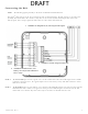
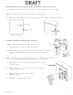
DRAFT Testing the Lock with the Access Control System NOTE: 1. With the hub connected to power and the access control system, the lock is tested with a known good credential to confirm it will open as desired when installed. REMOVE the battery cover from the lock body. 3. CONNECT the wire (the wire is keyed) from the reader to the socket in the lock battery compartment. 5. PRESENT a credential known to the access control system. 2. PASS the wire and shaft from the reader through the lock body. 4.
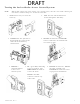
DRAFT ***CAUTION*** The Installer must ensure the lock can be opened before closing the cabinet at the end of these installation instructions. C Mounting the Lock NOTE: The K100-622 reader and lock body can be oriented in several ways to accommodate various cabinets and drawers. A B D 1. ESTABLISH the horizontal centerline of the latch. 1a. HOLD the lock body to the inside of the door and POSITION it generally where you would like it to mount. 1b.
DRAFT 2. TRANSFER the location of the inside wall of the cabinet to the door. 2a. MEASURE the horizontal distance between the inside edge of the cabinet and the door edge. NOTE: The drawn line depicts the location of the strike mounting surface. 2b. DRAW a line on the outside surface of the door, using the same distance away from the door edge. 2a Door edge 2b Cabinet/door front view 3. PLACE and USE the Lock/Reader Template. NOTE: Orientation will be reversed for a right hand door. 3a 3a.
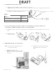
DRAFT 4. INSTALL the Shaft Extension. 4a. IF the cabinet door thickness is greater than ½” [12.70 mm], THEN INSTALL the Shaft Extension to the Antenna/Reader to ensure proper engagement into the lock. 4b. INSTALL the Shaft Extension to the shaft as shown in the figure and firmly TIGHTEN the screw. Shaft Extension 2-56 X 1-¼” [M1.4 x 0.3 x 31.50 mm] screw (provided) Table 1 Door Thickness Extension Shaft Used? 1/16” [1.59 mm] – ½” [12.70 mm] No > ½” [12.70 mm] – 1 ½” [38.10 mm] Yes 5.
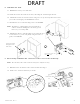
DRAFT 7. INSTALL the Antenna/Reader. ***CAUTION*** Pinching the wires may prevent the Reader and Lock from properly functioning. 7a. PLACE and HOLD the antenna/reader to the outside of cabinet, routing the wire through the 1/2” [12.70 mm] offset hole, and ENSURE the knob is in the locked position in the vertical. 7a NOTE: Using the Table 2 below will help determine the length of the top mount screw needed, based on the thickness of the cabinet door. 7b.
DRAFT 8. INSTALL the lock. 8a. REMOVE the battery cover from lock. 8b. PLACE the lock on the inside of the door, threading the cable through the lock. 8b. ATTACH the lock to the antenna/reader using two 8-32 [4.00 mm] lock mount screws (see Table 2 for length), and TIGHTEN the screws. 8c. INSTALL the two #6 self-threading screws and TIGHTEN. NOTE: The third #6 self-threading screw is important to achieve maximum holding force for doors greater than 5/8” [15.88 mm] thick. 8d.
10. INSTALL the Batteries. DRAFT NOTE: New batteries should always be used and inserted in the correct polarity position. 10a. INSTALL the battery and battery cover. 10b. INSTALL and TIGHTEN the screws. 10b 10a 11. PLACE the single-door Strike Plate Template. 11a. PEEL OFF the protective layer of the Strike Plate Template and ALIGN it to both the latch centerline and the edge of cabinet. 11b. DRILL two pilot holes as shown on template. 11c. REMOVE the template.
DRAFT 4. INSTALL the ShaftOPTIONAL Extension. DOUBLE-DOOR INSTALLATION 4a. IF the cabinet door thickness is greater than ½” [12.70 mm], 13. INSTALL the Double-Door Strike Plate MountingtoBracket THEN INSTALL the Shaft Extension to the Antenna/Reader ensure proper engagement into the lock. Shaft Extension : The double-door bracket to requires that door can be secured. NOTE 4b. INSTALL the Shaft Extension the shaft asone shown 2-56 X 1-¼” [M1.4 x 0.3 x 31.50 mm] in the figure and firmly TIGHTEN the screw.
DRAFT 7. INSTALL the Antenna/Reader. ***CAUTION*** Pinching the wires may prevent the Reader and Lock from properly functioning. 7a. PLACE and HOLD the antenna/reader to the outside of cabinet, routing the wire through the 1/2” [12.70 mm] offset hole, and ENSURE the knob is in the locked position in the vertical. 7a NOTE: Using the Table 2 below will help determine the length of the top mount screw needed, based on the thickness of the cabinet door. 7b.
DRAFT 8. INSTALL the lock. 8a. REMOVE the battery cover from lock. 8b. PLACE the lock on the inside of the door, threading the cable through the lock. 8b. ATTACH the lock to the antenna/reader using two 8-32 [4.00 mm] lock mount screws (see Table 2 for length), and TIGHTEN the screws. 8c. INSTALL the two #6 self-threading screws and TIGHTEN. NOTE: The third #6 self-threading screw is important to achieve maximum holding force for doors greater than 5/8” [15.88 mm] thick. 8d.
10. INSTALL the Batteries. DRAFT NOTE: New batteries should always be used and inserted in the correct polarity position. 10a. INSTALL the battery and battery cover. 10b. INSTALL and TIGHTEN the screws. 10b 10a 11. PLACE the single-door Strike Plate Template. 11a. PEEL OFF the protective layer of the Strike Plate Template and ALIGN it to both the latch centerline and the edge of cabinet. 11b. DRILL two pilot holes as shown on template. 11c. REMOVE the template.
DRAFT OPTIONAL DOUBLE-DOOR INSTALLATION 13. INSTALL the Double-Door Strike Plate Mounting Bracket NOTE: The double-door bracket requires that one door can be secured. 13a. PLACE the bracket on door, making sure it aligns with the mark made in Step 2c and the edge of the door. 13b. MARK the door. 13c. REMOVE the bracket and DRILL pilot holes at the two marks. 13d. INSTALL the bracket using the mounting screws provided. 13a 13b and 13c 14. INSTALL the double-door strike plate. 14a.
DRAFT WARNING FCC Statement This equipment has been tested and found to comply with the limits for a class B digital device, pursuant to part 15 of the FCC Rules. These limits are designed to provide reasonable protection against harmful interference in a residential installation. This equipment generates, uses, and can radiate radio frequency energy and if not installed and used in accordance with the instructions, may cause harmful interference to radio communications.
DRAFT HES, Inc. Phoenix, AZ 1.800.626.7590 ® KS100-640H Aperio Cabinet Lock Installation Instructions www.hesinnovations.
System Overview DRAFT The KS100-640 wireless server cabinet lock extends access control to a server cabinet without the complexity and expense of running wires. The KS100-640 cabinet lock connects to an access control system through the included communication hub. The communication hub connects to the access control system with Wiegand wiring typical of a Wiegand reader. When a credential card is presented to the reader on the lock, the request for access is sent wirelessly to the communication hub.
1. Locating the hub DRAFT It is recommended that the hub be mounted on the ceiling or near the top of a wall to reduce potential for interference. Note, the hub is not rated for use in plenum air spaces. For a stable and reliable radio link, it is recommended that the hub be located within fifty (50) feet of the lock. A maximum of two interior walls between the hub and lock is recommended A B Recommended locations: A: Ceiling Mount B: Wall Mount 2. Mounting the Hub.
3. Wiring the Hub. DRAFT The Aperio Hub connects to the Access Control system via Wiegand wiring. The hub requires 8-24VDC power (250mA). The hub includes two form C relays that can be used to transmit door position and tamper detection signals. The hub connects to the cabinet lock wirelessly. *Note: the DPS signal will trigger when either the latch handle or the door is out of position. Both the latch handle and door must be in position for a secure DPS signal.
DRAFT 6-pin 7-pin 2. 1. INSERT cam into SFIC using the included spacers with 6-pin SFICs. 3. INSERT SFIC into lock REMOVE plug from handle 5. Preparing the Rack LOCATE the 25mm x 150mm lock cutout on the door, some doors may require modification. 1. VERIFY 48V POE power is available at the rack. 2. RE_USE the existing cam if possible. 3. Three cams are supplied. CAM CAM LENGTH CAM DEPTH CAM 1 38mm [1-1/2"] 16mm [5/8"] CAM 2 38mm [1-1/2"] 24mm [15/16"] CAM 3 45mm [1-3/4"] 22.
DRAFT 6. Installing the lock on the door 1. SLIDE lock into cutout. 2. SELECT Power source: (A. 24VDC Supply or B. 48V PoE) CONNECT 24 VDC cable to lock. A B 24VDC cable CONNECT 24 VDC power supply (not provided) to 24 VDC cable. PLUG 48V PoE RJ-45 cable into lock. Lock will beep once and perform self test. Red wire (24VDC), black wire (Ground) 3. Optional: The DPS signal is closed when the handle is resting in its locked position.
DRAFT 7. Installing the Handing Selector NOTE: Be careful not to insert/snap the handle all the way in as the lever will lock. Door edge 1. INSERT handing selector into lock. 2. 3. POSITION the arrows to point toward the door edge as shown above. SECURE cam with screw. 8. Testing the Lock with the Access Control System TEST the lock with a known good credential to confirm it will open as desired when installed. Part Number 3080006.009 Rev. C 1.
FCC Statement DRAFT This equipment has been tested and found to comply with the limits for a class B digital device, pursuant to part 15 of the FCC Rules. These limits are designed to provide reasonable protection against harmful interference in a residential installation. This equipment generates, uses, and can radiate radio frequency energy and if not installed and used in accordance with the instructions, may cause harmful interference to radio communications.
DRAFT R100H Aperio® Reader Installation Instructions Securitron Magnalock Corp. Phoenix, AZ 800.624.5625 www.securitron.com Package Contents Aperio Hub Hub Mounting Bracket Reader CR2 Battery Screws Hex Wrench Glue Recommended Tools Approved Credential (i.e., iCLASS or Prox ID card) Level Optional Dress Cover: R100-DCA Pencil, wax pencil Optional Clamping device Product Specifications Hub Power Requirement: 8–24 VDC, 250 mA Wireless Frequency: 2.4 GHz, IEEE 802.15.
DRAFT Locate the Hub NOTE: B The hub is not rated for use in plenum air spaces. A 1. ENSURE the hub is located: • Near the top of a wall or on the ceiling to reduce potential for interference. • Within fifty (50) feet of the lock. • Where there is a maximum of two interior walls between the hub and lock. • In the interior lobby, for a glass entryway. Mount the Hub 1. MOUNT the hub on a single or double gang box using the included adapter plate.
Prepare the R100 DRAFT 1. Before starting, MARK the position using a level. 2. HOLD the reader body on the outside of the window and POSITION it generally where you would like it to mount. The cover is pulled up while pressing on the LED A pencil is used to mark this point on the window Insert Battery Battery 1. INSTALL the battery, ensuring correct orientation. 2. VERIFY the reader self tests and beeps once.
DRAFT 3. PERFORM the following if the R100 is mounted using wood screws. a. SEPARATE the components by gripping the electronic module at the noted side areas. b. ROCK UP, PULL DOWN, and LIFT OUT. c. PRE-DRILL through the mounting plate at the four corners and INSERT wood screws. d. REATTACH electronic module by sliding the top under the mounting plate’s raised edges and PRESS DOWN firmly until it clicks. Wood screws Mounting Plate Side grip areas Test the Reader 1.
FCC Statement DRAFT This equipment has been tested and found to comply with the limits for a class B digital device, pursuant to part 15 of the FCC Rules. These limits are designed to provide reasonable protection against harmful interference in a residential installation. This equipment generates, uses, and can radiate radio frequency energy and if not installed and used in accordance with the instructions, may cause harmful interference to radio communications.