
User Manual

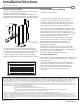
Table Of Contents

3
8
9
1
2
Prox Module
#6-32 Module Mounting Screws (for optional strike mount)
Reader/Antenna Body
Reader/Antenna Mounting Screws
Reader/Antenna Cover
1
2
3
4
5
6
7
24” Cable (connecting reader/antenna and strike)
8
9
2 pin DPS & LBM Pigtail Connector
11
Dielectric Grease (for humid applications)
10
4 pin 12V Strike Power Pigtail
8 pin Connector (Data Module) Prox Pigtail
RF0010
Installation Instructions
Prox Module
HES, Inc.
22630 N. 17th Ave.
Phoenix, AZ 85027
800-626-7590
The Prox Module can either be supported by
the electrical connection to the Electric Strike,
or by mounting it directly to the back of several
HES Electric Strikes using the #6-32 Module
Mounting Screws. Do not attempt to support
the Prox Module with the 24” Antenna Cable.
Access Control System
Control Panel and Power Supply
(By others)
8 Pin Connector (Data Module)
Red (+) Board Power
Black ( ) Board Power
Green Data 0
White Data 1
Yellow LED/Buzzer
Blue Not Used
Orange Not Used
Brown Not Used
2 Pin Connector (Door Position Switch)
Wire plugs into Hybrid Electric Strike
Wiring Diagram
-
2 pin Connector (Strike Module)
Tan Common
Pink Door Closed and Latch Engaged
4 Pin Connector (12V Strike Power)
Red (12VDC +) Strike Power
Black (−) Strike Power
4 Pin Connector (24V Strike Power)
Violet (24VDC +) Strike Power
Black
(−) Strike Power
OR
Dielectric
Grease
6
11
7
4
5
10
Door Position Sensor (DPS)
To Electric Strike