
User Guide
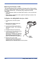
Table Of Contents
- 4600g, 4600r, 4800i User’s Guide
- Table of Contents
- Getting Started
- About This Manual
- Unpacking the Imager
- Imager Models
- Imager Identification
- Connecting the Imager with Keyboard Wedge
- Connecting the Imager with USB
- Connecting the Imager with RS-232 Serial Port
- Connecting the Imager with RS-232 Wedge
- Programming the Interface - Plug and Play
- Keyboard Wedge Connection
- USB Connection
- RS-232 Serial Port Connection
- Serial Wedge Data Transmission Port
- IBM 4683 Ports 5B, 9B, and 17 Connection
- Wand Emulation Connection
- Reading Techniques
- Terminal Interfaces
- Output
- Good Read Indicators
- Good Read Delay
- User-Specified Good Read Delay
- Trigger Modes
- Scan Stand Mode
- Presentation Mode
- Streaming Presentation™ Mode
- Hands Free Time-Out
- Reread Delay
- User-Specified Reread Delay
- LED Power Level
- Illumination Lights
- Imager Time-Out
- Aimer Delay
- Aimer Mode
- Centering
- Decode Search Mode
- Preferred Symbology
- Output Sequence Overview
- Multiple Symbols
- No Read
- Print Weight
- Video Reverse
- Working Orientation
- Data Editing
- Data Formatting
- Secondary Interface
- Symbologies
- Message Length Description
- Codabar Start / Stop Characters
- Codabar Check Character
- Codabar Concatenation
- Codabar Message Length
- Code 39 Start / Stop Characters
- Code 39 Check Character
- Code 39 Message Length
- Code 39 Append
- Code 32 Pharmaceutical (PARAF)
- Full ASCII
- Code 39 Code Page
- Check Digit
- Interleaved 2 of 5 Message Length
- Code 93 Message Length
- Code 93 Code Page
- Straight 2 of 5 Industrial Message Length
- Straight 2 of 5 IATA Message Length
- Matrix 2 of 5 Message Length
- Check Digits Required
- Code 11 Message Length
- ISBT 128 Concatenation
- Code 128 Message Length
- Code 128 Code Page
- Telepen Output
- Telepen Message Length
- UPC-A Check Digit
- UPC-A Number System
- UPC-A Addenda
- UPC-A Addenda Required
- UPC-A Addenda Separator
- UPC-E0
- UPC-E0 Expand
- UPC-E0 Addenda Required
- UPC-E0 Addenda Separator
- UPC-E0 Check Digit
- UPC-E0 Number System
- UPC-E0 Addenda
- EAN/JAN-13 Check Digit
- EAN/JAN-13 Addenda
- EAN/JAN-13 Addenda Required
- EAN/JAN-13 Addenda Separator
- ISBN Translate
- EAN/JAN-8 Check Digit
- EAN/JAN-8 Addenda
- EAN/JAN-8 Addenda Required
- EAN/JAN-8 Addenda Separator
- MSI Check Character
- MSI Message Length
- Plessey Message Length
- RSS Expanded Message Length
- PosiCode Message Length
- Codablock F Message Length
- Code 16K Message Length
- Code 49 Message Length
- PDF417 Message Length
- MicroPDF417 Message Length
- UPC/EAN Version
- EAN.UCC Composite Code Message Length
- 4-CB (4-State Customer Bar Code)
- ID-tag (UPU 4-State)
- Postnet
- Planet Code
- British Post
- Canadian Post
- Kix (Netherlands) Post
- Australian Post
- Australian Post Interpretation
- Japanese Post
- China Post Message Length
- Korea Post Message Length
- QR Code Message Length
- Data Matrix Message Length
- MaxiCode Message Length
- Aztec Code Message Length
- Aztec Runes
- Message Length Description
- Imaging Commands
- OCR Programming
- Interface Keys
- Utilities
- Serial Programming Commands
- Product Specifications
- Maintenance
- Customer Support
4600g, 4600r, 4800i User’s Guide 14 - 3
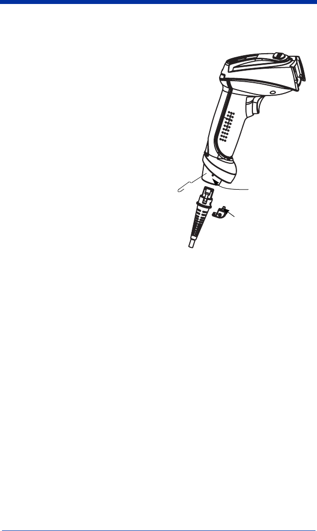
To Replace the 4800i Interface Cable:
1. Turn the power to the host system
OFF.
2. Disconnect the imager’s cable from
the terminal or computer.
3. Use a screwdriver to unscrew the cord
lock from the base of the imager.
4. Locate the small hole on the side of
the imager’s handle. This is the cable
release.
5. Straighten one end of a paper clip.
6. Insert the end of the paper clip into the
small hole and press in. This
depresses the retention tab, releasing
the connector. Pull the connector out
while maintaining pressure on the
paper clip, then remove the paper clip.
7. Replace with the new cable.
Insert the connector into the opening
and press firmly. The connector is
keyed to go in only one way, and will click into place.
8. Screw the cord lock back in place over the cord.
Troubleshooting
The imager automatically performs self-tests whenever you turn it on. If your
imager is not functioning properly, review the following Troubleshooting Guide to
try to isolate the problem.
Is the power on? Is the red aiming illumination line on?
If the red aiming illumination line isn’t illuminated, check that:
• The cable is connected properly.
• The host system power is on (if external power isn’t used).
• The trigger works.
Is the imager having trouble reading your symbols?
If the imager isn’t reading symbols well, check that the symbols:
• Aren’t smeared, rough, scratched, or exhibiting voids.
• Aren’t coated with frost or water droplets on the surface.
• Are enabled in the imager or in the decoder to which the imager connects.
Cable
Release
Cord lock