
User Guide
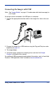
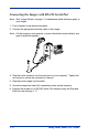
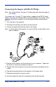
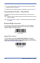
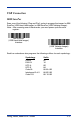
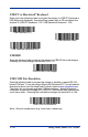
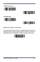
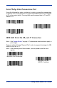

Table Of Contents
- 4600g, 4600r, 4800i User’s Guide
- Table of Contents
- Getting Started
- About This Manual
- Unpacking the Imager
- Imager Models
- Imager Identification
- Connecting the Imager with Keyboard Wedge
- Connecting the Imager with USB
- Connecting the Imager with RS-232 Serial Port
- Connecting the Imager with RS-232 Wedge
- Programming the Interface - Plug and Play
- Keyboard Wedge Connection
- USB Connection
- RS-232 Serial Port Connection
- Serial Wedge Data Transmission Port
- IBM 4683 Ports 5B, 9B, and 17 Connection
- Wand Emulation Connection
- Reading Techniques
- Terminal Interfaces
- Output
- Good Read Indicators
- Good Read Delay
- User-Specified Good Read Delay
- Trigger Modes
- Scan Stand Mode
- Presentation Mode
- Streaming Presentation™ Mode
- Hands Free Time-Out
- Reread Delay
- User-Specified Reread Delay
- LED Power Level
- Illumination Lights
- Imager Time-Out
- Aimer Delay
- Aimer Mode
- Centering
- Decode Search Mode
- Preferred Symbology
- Output Sequence Overview
- Multiple Symbols
- No Read
- Print Weight
- Video Reverse
- Working Orientation
- Data Editing
- Data Formatting
- Secondary Interface
- Symbologies
- Message Length Description
- Codabar Start / Stop Characters
- Codabar Check Character
- Codabar Concatenation
- Codabar Message Length
- Code 39 Start / Stop Characters
- Code 39 Check Character
- Code 39 Message Length
- Code 39 Append
- Code 32 Pharmaceutical (PARAF)
- Full ASCII
- Code 39 Code Page
- Check Digit
- Interleaved 2 of 5 Message Length
- Code 93 Message Length
- Code 93 Code Page
- Straight 2 of 5 Industrial Message Length
- Straight 2 of 5 IATA Message Length
- Matrix 2 of 5 Message Length
- Check Digits Required
- Code 11 Message Length
- ISBT 128 Concatenation
- Code 128 Message Length
- Code 128 Code Page
- Telepen Output
- Telepen Message Length
- UPC-A Check Digit
- UPC-A Number System
- UPC-A Addenda
- UPC-A Addenda Required
- UPC-A Addenda Separator
- UPC-E0
- UPC-E0 Expand
- UPC-E0 Addenda Required
- UPC-E0 Addenda Separator
- UPC-E0 Check Digit
- UPC-E0 Number System
- UPC-E0 Addenda
- EAN/JAN-13 Check Digit
- EAN/JAN-13 Addenda
- EAN/JAN-13 Addenda Required
- EAN/JAN-13 Addenda Separator
- ISBN Translate
- EAN/JAN-8 Check Digit
- EAN/JAN-8 Addenda
- EAN/JAN-8 Addenda Required
- EAN/JAN-8 Addenda Separator
- MSI Check Character
- MSI Message Length
- Plessey Message Length
- RSS Expanded Message Length
- PosiCode Message Length
- Codablock F Message Length
- Code 16K Message Length
- Code 49 Message Length
- PDF417 Message Length
- MicroPDF417 Message Length
- UPC/EAN Version
- EAN.UCC Composite Code Message Length
- 4-CB (4-State Customer Bar Code)
- ID-tag (UPU 4-State)
- Postnet
- Planet Code
- British Post
- Canadian Post
- Kix (Netherlands) Post
- Australian Post
- Australian Post Interpretation
- Japanese Post
- China Post Message Length
- Korea Post Message Length
- QR Code Message Length
- Data Matrix Message Length
- MaxiCode Message Length
- Aztec Code Message Length
- Aztec Runes
- Message Length Description
- Imaging Commands
- OCR Programming
- Interface Keys
- Utilities
- Serial Programming Commands
- Product Specifications
- Maintenance
- Customer Support
4600g, 4600r, 4800i User’s Guide 1 - 7
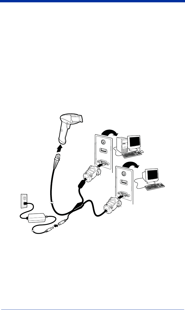
Connecting the Imager with RS-232 Wedge
Note: See "Imager Models" on page 1-2 to determine which interfaces apply to
your imager.
Your imager uses True and TTL signal levels to wedge into an RS-232 serial
network. Use only serial wedge cables to prevent damage to the imager. Refer
to RS-232 Baud Rate on page 2-9 to set the baud rate and communications
protocol.
1. Turn off power to the computer.
2. Disconnect the existing serial cable from the computer.
3. Connect the appropriate interface cable to the imager.
Note: For the imager to work properly, you must have the correct cable for your
type of computer.
4. Plug the serial connector into the serial port on your computer. Tighten the
two screws to secure the connector to the port.
5. Plug the other serial connector into the host connection and tighten the two
screws.
6. Plug the power pack cable into the receptor on the imager cable.
7. Plug the power pack into a power source.
8. Once the imager has been fully connected, power up the computer.
Host
Terminal