
User Guide
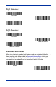

Table Of Contents
- 4600g, 4600r, 4800i User’s Guide
- Table of Contents
- Getting Started
- About This Manual
- Unpacking the Imager
- Imager Models
- Imager Identification
- Connecting the Imager with Keyboard Wedge
- Connecting the Imager with USB
- Connecting the Imager with RS-232 Serial Port
- Connecting the Imager with RS-232 Wedge
- Programming the Interface - Plug and Play
- Keyboard Wedge Connection
- USB Connection
- RS-232 Serial Port Connection
- Serial Wedge Data Transmission Port
- IBM 4683 Ports 5B, 9B, and 17 Connection
- Wand Emulation Connection
- Reading Techniques
- Terminal Interfaces
- Output
- Good Read Indicators
- Good Read Delay
- User-Specified Good Read Delay
- Trigger Modes
- Scan Stand Mode
- Presentation Mode
- Streaming Presentation™ Mode
- Hands Free Time-Out
- Reread Delay
- User-Specified Reread Delay
- LED Power Level
- Illumination Lights
- Imager Time-Out
- Aimer Delay
- Aimer Mode
- Centering
- Decode Search Mode
- Preferred Symbology
- Output Sequence Overview
- Multiple Symbols
- No Read
- Print Weight
- Video Reverse
- Working Orientation
- Data Editing
- Data Formatting
- Secondary Interface
- Symbologies
- Message Length Description
- Codabar Start / Stop Characters
- Codabar Check Character
- Codabar Concatenation
- Codabar Message Length
- Code 39 Start / Stop Characters
- Code 39 Check Character
- Code 39 Message Length
- Code 39 Append
- Code 32 Pharmaceutical (PARAF)
- Full ASCII
- Code 39 Code Page
- Check Digit
- Interleaved 2 of 5 Message Length
- Code 93 Message Length
- Code 93 Code Page
- Straight 2 of 5 Industrial Message Length
- Straight 2 of 5 IATA Message Length
- Matrix 2 of 5 Message Length
- Check Digits Required
- Code 11 Message Length
- ISBT 128 Concatenation
- Code 128 Message Length
- Code 128 Code Page
- Telepen Output
- Telepen Message Length
- UPC-A Check Digit
- UPC-A Number System
- UPC-A Addenda
- UPC-A Addenda Required
- UPC-A Addenda Separator
- UPC-E0
- UPC-E0 Expand
- UPC-E0 Addenda Required
- UPC-E0 Addenda Separator
- UPC-E0 Check Digit
- UPC-E0 Number System
- UPC-E0 Addenda
- EAN/JAN-13 Check Digit
- EAN/JAN-13 Addenda
- EAN/JAN-13 Addenda Required
- EAN/JAN-13 Addenda Separator
- ISBN Translate
- EAN/JAN-8 Check Digit
- EAN/JAN-8 Addenda
- EAN/JAN-8 Addenda Required
- EAN/JAN-8 Addenda Separator
- MSI Check Character
- MSI Message Length
- Plessey Message Length
- RSS Expanded Message Length
- PosiCode Message Length
- Codablock F Message Length
- Code 16K Message Length
- Code 49 Message Length
- PDF417 Message Length
- MicroPDF417 Message Length
- UPC/EAN Version
- EAN.UCC Composite Code Message Length
- 4-CB (4-State Customer Bar Code)
- ID-tag (UPU 4-State)
- Postnet
- Planet Code
- British Post
- Canadian Post
- Kix (Netherlands) Post
- Australian Post
- Australian Post Interpretation
- Japanese Post
- China Post Message Length
- Korea Post Message Length
- QR Code Message Length
- Data Matrix Message Length
- MaxiCode Message Length
- Aztec Code Message Length
- Aztec Runes
- Message Length Description
- Imaging Commands
- OCR Programming
- Interface Keys
- Utilities
- Serial Programming Commands
- Product Specifications
- Maintenance
- Customer Support

4600g, 4600r, 4800i User’s Guide 5 - 1
5
Data Formatting
Data Format Editor Introduction
You may use the Data Format Editor to change the imager’s output. For
example, you can use the Data Format Editor to insert characters at certain
points in bar code data as it is scanned. The selections in the following pages
are used only if you wish to alter the output.
Default Data Format setting = None.
Normally, when you scan a bar code, it gets outputted automatically; however
when you do a format, you must use a “send” command (see Send Commands
on page 5-2) within the format program to output data.
Multiple formats may be programmed into the imager. They are stacked in the
order in which they are entered. However, the following list presents the order
in which formats are applied:
1. Specific Term ID, Actual Code ID, Actual Length
2. Specific Term ID, Actual Code ID, Universal Length
3. Specific Term ID, Universal Code ID, Actual Length
4. Specific Term ID, Universal Code ID, Universal Length
5. Universal Term ID, Actual Code ID, Actual Length
6. Universal Term ID, Actual Code ID, Universal Length
7. Universal Term ID, Universal Code ID, Actual Length
8. Universal Term ID, Universal Code ID, Universal Length
If you have changed data format settings, and wish to clear all formats and return
to the factory defaults, scan the Default Data Format code on page 5-5.
To Add a Data Format
Step 1. Scan the Enter Data Format symbol (page 5-5).
Step 2. Primary/Alternate Format
Determine if this will be your primary data format, or one of 3 alternate
formats. (Alternate formats allow you “single shot” capability to scan
one bar code using a different data format. After the one bar code has
been read, the imager reverts to the primary data format. See page 5-
6.) If you are programming the primary format, scan 0 using the Pro-
gramming Chart inside the back cover of this manual. If you are pro-
gramming an alternate format, scan 1, 2, or 3, depending on the
alternate format you are programming.
Step 3. Terminal Type
Refer to Supported Terminals (page 2-2) and locate the Terminal ID
number for your PC. Scan three numeric bar codes on the inside back
cover to program the imager for your terminal ID (you must enter 3 dig-
its). For example, scan 0 0 3 for an AT wedge.
Note: The wildcard for all terminal types is 099.