
User Guide
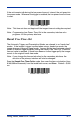
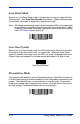
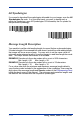
Table Of Contents
- 4600g, 4600r, 4800i User’s Guide
- Table of Contents
- Getting Started
- About This Manual
- Unpacking the Imager
- Imager Models
- Imager Identification
- Connecting the Imager with Keyboard Wedge
- Connecting the Imager with USB
- Connecting the Imager with RS-232 Serial Port
- Connecting the Imager with RS-232 Wedge
- Programming the Interface - Plug and Play
- Keyboard Wedge Connection
- USB Connection
- RS-232 Serial Port Connection
- Serial Wedge Data Transmission Port
- IBM 4683 Ports 5B, 9B, and 17 Connection
- Wand Emulation Connection
- Reading Techniques
- Terminal Interfaces
- Output
- Good Read Indicators
- Good Read Delay
- User-Specified Good Read Delay
- Trigger Modes
- Scan Stand Mode
- Presentation Mode
- Streaming Presentation™ Mode
- Hands Free Time-Out
- Reread Delay
- User-Specified Reread Delay
- LED Power Level
- Illumination Lights
- Imager Time-Out
- Aimer Delay
- Aimer Mode
- Centering
- Decode Search Mode
- Preferred Symbology
- Output Sequence Overview
- Multiple Symbols
- No Read
- Print Weight
- Video Reverse
- Working Orientation
- Data Editing
- Data Formatting
- Secondary Interface
- Symbologies
- Message Length Description
- Codabar Start / Stop Characters
- Codabar Check Character
- Codabar Concatenation
- Codabar Message Length
- Code 39 Start / Stop Characters
- Code 39 Check Character
- Code 39 Message Length
- Code 39 Append
- Code 32 Pharmaceutical (PARAF)
- Full ASCII
- Code 39 Code Page
- Check Digit
- Interleaved 2 of 5 Message Length
- Code 93 Message Length
- Code 93 Code Page
- Straight 2 of 5 Industrial Message Length
- Straight 2 of 5 IATA Message Length
- Matrix 2 of 5 Message Length
- Check Digits Required
- Code 11 Message Length
- ISBT 128 Concatenation
- Code 128 Message Length
- Code 128 Code Page
- Telepen Output
- Telepen Message Length
- UPC-A Check Digit
- UPC-A Number System
- UPC-A Addenda
- UPC-A Addenda Required
- UPC-A Addenda Separator
- UPC-E0
- UPC-E0 Expand
- UPC-E0 Addenda Required
- UPC-E0 Addenda Separator
- UPC-E0 Check Digit
- UPC-E0 Number System
- UPC-E0 Addenda
- EAN/JAN-13 Check Digit
- EAN/JAN-13 Addenda
- EAN/JAN-13 Addenda Required
- EAN/JAN-13 Addenda Separator
- ISBN Translate
- EAN/JAN-8 Check Digit
- EAN/JAN-8 Addenda
- EAN/JAN-8 Addenda Required
- EAN/JAN-8 Addenda Separator
- MSI Check Character
- MSI Message Length
- Plessey Message Length
- RSS Expanded Message Length
- PosiCode Message Length
- Codablock F Message Length
- Code 16K Message Length
- Code 49 Message Length
- PDF417 Message Length
- MicroPDF417 Message Length
- UPC/EAN Version
- EAN.UCC Composite Code Message Length
- 4-CB (4-State Customer Bar Code)
- ID-tag (UPU 4-State)
- Postnet
- Planet Code
- British Post
- Canadian Post
- Kix (Netherlands) Post
- Australian Post
- Australian Post Interpretation
- Japanese Post
- China Post Message Length
- Korea Post Message Length
- QR Code Message Length
- Data Matrix Message Length
- MaxiCode Message Length
- Aztec Code Message Length
- Aztec Runes
- Message Length Description
- Imaging Commands
- OCR Programming
- Interface Keys
- Utilities
- Serial Programming Commands
- Product Specifications
- Maintenance
- Customer Support

6 - 8 4600g, 4600r, 4800i User’s Guide
Scan Stand Mode
When a unit is in Scan Stand mode, it remains idle as long as it sees the Scan
Stand symbol. (See
Scan Stand Symbol
that follows.) When a different code
is presented, the Imager is triggered to read the new code.
Note: The imager automatically adjusts the illumination LEDs to the lowest light
level possible to maintain a good lock on the Scan Stand symbol. When
a symbol is presented, the imager’s light levels adjust to the saved setting
(see LED Power Level on page 3-9).
Scan Stand Symbol
When a unit is in Scan Stand mode, the LEDs shine at the Scan Stand symbol
on the base of the stand which tells it to remain idle.
When the Scan Stand
symbol is covered, the imager turns the LEDs on at the configured power level
(Default High) and attempts to find and decode bar codes in its field of view.
Presentation Mode
This programs the imager to work in Presentation mode. The LEDs are either off
or at the lowest power for ambient conditions until a bar code is presented to the
imager. Then the LEDs turn on automatically to read the code. Presentation
Mode uses ambient light to detect the bar codes. If the light level in the room is
not high enough, Presentation Mode may not work properly.
Scan Stand Mode
Scan Stand Symbol
Presentation Mode