Decoded Output
Disclaimer Welch Allyn reserves the right to make changes in specifications and other information contained in this document without prior notice, and the reader should in all cases consult Welch Allyn to determine whether any such changes have been made. The information in this publication does not represent a commitment on the part of Welch Allyn.
This device complies with part 15 of the FCC Rules. Operation is subject to the following two conditions: (1) this device may not cause harmful interference, and (2) this device must accept any interference received, including interference that may cause undesired operation. FCC Class B Compliance Statement This equipment has been tested and found to comply with the limits for a Class B digital device pursuant to part 15 of the FCC Rules.
The CE mark on the product indicates that the system has been tested to and conforms with the provisions noted within the 89/336/EEC Electromagnetic Compatibility Directive and the 73/23/EEC Low Voltage Directive. For further information, please contact: Welch Allyn Ltd. 1st Floor Dallam Court Dallam Lane Warrington, Cheshire WA2 7LT England Welch Allyn shall not be liable for use of our product with equipment (i.e., power supplies, personal computers, etc.
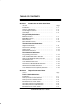
TABLE OF CONTENTS Section 1 Introduction & Quick Start Menu Section Introduction . . . . . . . . . . . . . . . . . . . . . . . . . . . . . . . . . . . Scanner Identification . . . . . . . . . . . . . . . . . . . . . . . . . . Connecting the Scanner . . . . . . . . . . . . . . . . . . . . . . . . Scan Maps . . . . . . . . . . . . . . . . . . . . . . . . . . . . . . . . . . . . Page 1–1 1–2 1–3 1–4 Plug and Play Selections IBM PC Interface . . . . . . . . . . . . . . . . . . . . . . . . . . . . . .
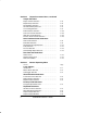
Section 2 Output Parameters Menu, continued Output Selections Beeper Volume Selection . . . . . . . . . . . . . . . . . . . . . . . Output Delays Selection . . . . . . . . . . . . . . . . . . . . . . . . Reread Delay Selection . . . . . . . . . . . . . . . . . . . . . . . . . Good Read Delay Selection . . . . . . . . . . . . . . . . . . . . . Laser Voting Selection . . . . . . . . . . . . . . . . . . . . . . . . . . Buffered Scans Selection . . . . . . . . . . . . . . . . . . . . . . . Code I.D.
Section 4 Symbology Menu Section Page Industrial Symbology Selections Introduction . . . . . . . . . . . . . . . . . . . . . . . . . . . . . . . . . . . Codabar Selection . . . . . . . . . . . . . . . . . . . . . . . . . . . . . Code 39 Selection . . . . . . . . . . . . . . . . . . . . . . . . . . . . . Code 93 Selection . . . . . . . . . . . . . . . . . . . . . . . . . . . . . Interleaved 2 of 5 Selection . . . . . . . . . . . . . . . . . . . . . Matrix 2 of 5 Selection . . . . . . . . . . . . . . . .
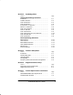
Section 8 Maintenance and Troubleshooting Section Page Maintenance . . . . . . . . . . . . . . . . . . . . . . . . . . . . . . . . . . Troubleshooting . . . . . . . . . . . . . . . . . . . . . . . . . . . . . . . 8–1 8–3 Section 9 Customer Service Section Page Obtaining Factory Service . . . . . . . . . . . . . . . . . . . . . . . Technical Support . . . . . . . . . . . . . . . . . . . . . . . . . . . . . . Limited Warranty . . . . . . . . . . . . . . . . . . . . . . . . . . . . . . .
Section 1 Introduction Introduction & Quick Start Menu Your scanner provides high value performance in an economical, durable solution for a wide variety of bar code data collection applications. The scanner contains Welch Allyn’s Instant Interface module, which integrates aggressive (“snappy”) decoding, advanced data editing and formatting capabilities, and multiple interface connectivity. The scanner recognizes and decodes 14 industry-standard bar code symbologies.
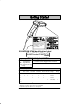
Scanner Identification Manufactured Month/Year Model Number 5X00/A-12 Serial Number 12345 Rev = 1.
Connecting the Scanner Install the scanner by following the steps shown below: ➊ Turn off the power to the host system. ➋ Connect the interface cable to the scanner and to the terminal/computer. 3 Disconnect 2 1 Keyboard Wedge Interface Example (Cable, Keyboard, and Terminal will vary.) ➌ Turn on the power to the host system. ➍ Program your scanner to work with your terminal or computer by scanning the Terminal Set–Up Codes.
In. Cm. 9.65 24.511 Typical Performance at 20°C for SCANTEAM 5700/A 19.3” 5 mil 2.5 3.5 7.5 mil 2 7 13 mil 1 9.65 24.511 14 20mil 1.5 40 mil 18 3.5 26 55 mil 4 31 In. 0 Cm. 0 2 4 6 8 10 12 14 16 18 20 22 5.08 10.2 15.2 20.3 25.4 30.5 35.6. 40.6 45.7 50.8 55.9 24 26 61 66 Typical Depth of Field in Inches/Centimeters 1–4 SCANTEAM 5700 User’s Guide 28 30 32 71.1 76.2 81.
Typical Performance at 20°C for SCANTEAM 5700/HD In. Cm. 2 5.08 1 2.54 0 0 1 2.54 2 5.08 2.8” 2.0” 3” 3 mil 1.0 2.5 5 mil .5 4.0 7.5 mil .5 4.5 10 mil .5 5.5 13 mil 1.0 6.0 In. 0 1 2 3 4 5 6 Cm. 0 2.54 5.08 7.62 10.16 12.7 15.
Typical Performance at 20°C for SCANTEAM 5700ALR 15 mil 22 43 30 mil 40 25 55 mil 88 99 123 100 mil 322 In. 0 Cm. 0 30 60 90 120 150 180 210 240 270 300 330 360 76.2 152.4 228.6 304.8 381.0 457.2 533.4 609.6 685.8 762.0 838.2 914.4 Typical Depth of Field in Inches/Centimeters 70 mil retroreflective – 68” (172.7 cm) – 13.5’ (411.5 cm) 100 mil retroreflective – 82” (208.3 cm) – 17.5’ (533.4 cm) 1–6 SCANTEAM 5700 User’s Guide In. 41 Cm. 104.1 30 76.2 20 50.8 10 25.4 0 0 10 25.4 20 50.
IBM PC, Wand Emulation Interface IBM PC AT and Compatibles Interface (Default) (also PS/2 30-286, 50, 55SX, 60, 70, 70-061, 70-121, 80) IBM PS/2 and Compatibles Interface ( for PS/2 25, 30 models) IBM PC XT and Compatibles Interface These bar codes also program a carriage return (CR) suffix. Wand Emulation (Code 39 Format) Interface Wand Emulation (Same Code Format) Interface [ [ Supports Code 39, UPC, EAN, Code 128, Interleaved 2 of 5, and Codabar. All other codes output as Code 39.
IBM 4683 Interface IBM 4683 Port 5B Interface IBM 4683 Port 9B HHBCR–1 Interface IBM 4683 Port 9B HHBCR–2 Interface IBM 4683 Port 17 Interface These bar codes also program the following parameters: Symbology EAN 8 EAN 13 UPC A UPC E 1–8 Suffix 0C 16 0D 0A Symbology Code 39 I 2 of 5 Code 128 SCANTEAM 5700 User’s Guide Prefix 00 0A 0B 00 0D 0B 00 18 0B
OCIA Interface Spectra-Physics OCIA Interface The bar code above also programs the following parameters: Symbology EAN 8 EAN 13 Suffix 06 06 06 Symbology UPC A UPC E Prefix 01 05 NCR OCIA Short Form Format (Eight Bit) Interface The bar code above also programs the following parameters: Symbology EAN 8 EAN 13 Suffix 0F 0F 0F Symbology UPC A UPC E Prefix 0A 0E NCR OCIA Long Form Format (Nine Bit) Interface The bar code above also programs the following parameters: Symbology EAN 8 EAN 13 UPC A UPC
OCR, RS232 Interface Fujitsu OCR Interface The bar code above also programs the following parameters: Symbology EAN 8 EAN 13 I 2 of 5 Suffix Symbology 17 UPC A 17 UPC E 03 (Application Dependent) Prefix 17 17 IBM OCR (Port 21) Interface The bar code above also programs the following parameters: Symbology EAN 8 EAN 13 Code 128 Suffix 0C 16 1D Symbology UPC A UPC E Prefix 0D 0A RS-232 Interface The bar code above also programs the following parameters: Programmable Option Baud Rate Parity Data Form
If your terminal is not one of the Plug and Play options, you must program one of the terminals listed below. To program the terminal interface, scan the Program Terminal Interface bar code below, then scan the appropriate two digit Terminal I.D. code from the Programming Chart on the inside back cover of this manual.
Supported Terminals Terminal Model(s) ICL IDEAS ITT Lee Data Link Mac 300 9271 IIS MC–5 OCIA OCR Olivetti Olivetti Qume ANSI M19, M24, M28, M200 240, 250, 290, 380, P500 QVT 61, 62, 70, 191, 321, 322 Terminal I.D.
Reset Factory Settings Scanning the Factory Default Settings bar code resets the scanner to the original factory settings, clearing any programming changes you may have made. Factory Default Settings Status Check Scan the Show Software Revision bar code to transmit the software revision level to the host terminal. The software revision will be printed out as “WA34310XXX.” (The “X’s” will vary according to the firmware ID.
Scanner models 5700–X1 and 5700/X–X2 support the dual interface option allowing you to connect to two different terminals by switching interface cables. This option supports interfaces common to portable data terminals. Dual Interface Programming Instructions To program the scanner for secondary interface, follow the steps below. (Dual Interface single scan programming codes are shown on the following pages.
Code 39 Wand Emulation Selection ✱ Code 39 Wand Emulation Selection Same Code Wand Emulation Selection Same Code Wand Emulation Selection [ RS-232 Selection RS-232 Selection Laser Emulation Selection Laser Emulation Selection Note: 5700–X3 units do not support Dual Interface. [ Supports Code 39, UPC, EAN, Code 128, Interleaved 2 of 5, and Codabar. All other codes output as Code 39.
Dual Interface Enable/Disable Selection Dual Interface Disable Selection lets you temporarily disable the dual interface selection, while retaining your secondary interface setup in memory. If you want to enable the secondary interface again, scan the Enable Dual Interface bar code below. ✱ Disable Enable Switched Power Mode Selections When this feature is enabled, the unit consumes less than 50 uA from its power line when the trigger is not pulled. When the trigger is pulled, it consumes normal power.
Section 2 Serial Interface Menu Introduction Use this chapter to program the output parameters for the Hand-Held Laser Scanner.
Primary Interface Prefix and Suffix The scanner transmits a decoded message after every successful bar code read. Prefix and Suffix characters are data characters you may assign to be sent before and after the transmitted bar code data. Transmitted data frame –> Prefix Bar Code Message Suffix Characters for the Prefix and Suffix are selected by their hexadecimal ASCII value, up to 12 characters each.
Primary Interface Prefix Selection Add Primary Prefix ] Clear All Primary Prefixes Clear One Primary Prefix ] Primary Interface Suffix Selection Add Primary Suffix ] Clear All Primary Suffixes Clear One Primary Suffix ] Exit Selection for Prefix / Suffix Save Current Prefix or Suffix Changes Discard Current Prefix or Suffix Changes ] One or more two-digit numbers are required after scanning this programming bar code. Please scan your selection on the Programming Chart (inside back cover).
Secondary (Dual) Interface Prefix and Suffix The scanner will transmit a decoded message after every successful bar code read. Prefix and Suffix characters are data characters you may assign to be sent before and after the transmitted bar code data. Transmitted data frame –> Prefix Bar Code Message Suffix Characters for the Prefix and Suffix are selected by their hexadecimal ASCII value, up to 12 characters each.
Secondary Interface Prefix Selection Add Secondary Prefix ] Clear All Secondary Prefixes Clear One Secondary Prefix ] Secondary Interface Suffix Selection Add Secondary Suffix ] Clear All Secondary Suffixes Clear One Secondary Suffix ] Exit Selection for Prefix / Suffix Save Current Prefix or Suffix Changes Discard Current Prefix or Suffix Changes ] One or more two-digit numbers are required after scanning this programming bar code. Scan your selection on the Programming Chart (inside back cover).
Prefix and Suffix Examples Example 1: Add Suffix for Specific Symbology You want to send a CR (carriage return) Suffix for UPC only. H Scan the Add Suffix Suffix Selection bar code. H The Symbology Chart indicates that the Hex value of UPC is “63”. Scan 6 and 3 on the Programming Chart (inside back cover). H A “CR” is equivalent to “0D” (see the Hex ASCII Chart). Scan 0 and D on the Programming Chart. H Scan the Save Current Suffix Changes Exit Selection bar code.
Symbology Chart Code ID [ Hex Value Code 11 h 68 Code 93 i 69 63 Code 128 j 6A d e 64 65 Matrix 2 of 5 Plessey m n 6D 6E Code 2 of 5 f 66 All Symbologies MSI g 67 (Prefix/Suffix Programming only.
✱ Default All Output Settings ✱ Beeper Volume Selection Off Low ✱ High Medium Output Delays Selection This selection provides control of the time delays between data output by the scanner to the host terminal. The actual delay is 5 milliseconds multiplied by the programmed value (00 – 99). Default = 00. Intercharacter Delay is the time delay between data characters output by the scanner to the host terminal.
Reread Delay Selection This selection allows you to set a time period that must pass before the scanner can read the same bar code again. Setting a reread delay protects against accidental rereads of the same bar code. Longer delays are effective in minimizing accidental rereads at POS (point of sale) terminals. Use shorter delays in applications where repetitive bar code scanning is required. ✱ Low (175 milliseconds) High (1.0 second) Medium (450 milliseconds) Extra High (2.
Buffered Scans Selection When enabled, this selection allows the scanner to accept a second scan while the current scan is transmitted to the host terminal (buffering of scanned data). When disabled, the scanner cannot accept additional scans until the current scan is transmitted to the host. Default = Enable. ✱ Enable Disable Code I.D. Transmit Selection This allows you to enable or disable transmission of a Code I.D. before the decoded bar code symbology.
✱ Default All Serial Communication Settings ✱ CTS Check Selection This selection allows you to select the software programming feature that checks for a CTS signal, if your application does not have a CTS I/O line. Default = Disable. Enable ✱ Disable Baud Rate Selection This selection sets the baud rate from 300 bits per second to 38,400 bits per second. Programming baud rate causes the data to be sent at the specified rate.
RS-232 Word Length Selection This selection allows you to set the RS-232 word length at seven or eight bits of data per character. The number of start and stop bits is fixed at one each. If an application requires only ASCII Hex characters 0 through 7F decimal (text, digits, and punctuation), select 7 data bits. For applications requiring use of the full ASCII set, select 8 data bits per character.
Protocol Selection This selection allows you to program the scanner for the protocol required by your application. The protocol is a set of rules concerning the exchange of data between serially communicating devices. The scanner supports Record, Xon / Xoff, and Ack / Nak protocols when receiving data from an RS-232 device. ✱ Record Xon / Xoff Ack / Nak Serial Wedge Output Selection This selection allows you to select the serial output direction required by your application.
Data Format Editor This selection provides editing of all input (scanned) data. All Industrial and Retail symbologies can be formatted. You may scan the Clear Data Format bar code if you are certain you want to delete or clear all formats. To make Data Format Editor selections, you must know the terminal type, code I.D., code length, and editor commands your application requires. Use the Alpha-numeric bar codes (inside back cover) to scan these options.
Status Check Scan the Show Formats bar code to transmit the existing Data Format Editor formats. One format per line will be printed out. Show Formats Require Data Format When disabled, the bar code data will be output to the host as scanned (including prefixes and suffixes). When enabled, all input data must conform to an edited format or the scanner will not transmit the input data to the host device.
Format Editor Commands Chart Send Commands F1 Send all characters followed by “XX” key or function code, starting from current cursor position. Syntax = F1XX (XX = HEX ASCII character or function code 00–FE HEX). F2 Send “NN” characters followed by “XX” key or function code, starting from current cursor position. Syntax = F2NNXX (NN = number of characters 00–99 DEC, XX = HEX ASCII character or function code 00–EF HEX).
Data Formatter Example You are using an IBM PC AT and are scanning a UPC A bar code with a five digit addenda (shown below). The bar code has a total of 18 characters, including the number system, the check digits, and a space between the main bar code data and the addenda bar code data. UPC A with 5 digit addenda 56098 0 12345 67890 5 For your application, you don’t want the space between the main bar code data and the addenda bar code data transmitted.
2–18 SCANTEAM 5700 User’s Guide
Introduction Use this chapter to program the Hand-Held Laser Scanner for General Operating features.
Marker Beam Selection When enabled, the scanner shows a marker or locator beam before the red scan line opens across a bar code and the scanning process begins. The marker beam, emitted by centering the optical scan mirror, appears as a bright spot of illumination that serves as an aiming guide when bar code targets are at a distance from the scanner. Note: Applies only to the 5700ALR product.
Transmission Rate Selection This programming selection sets the transmission rate from 10 ips (inches per second) to 300 ips if the scanner is in Wand Emulation mode. Programming the transmission rate causes the data to be sent at the specified rate. The programmed transmission rate must be compatible with the device receiving the bar code data. Default = 25 ips (inches per second).
Foreign Keyboard Selection This programming selection allows you to re-map the keyboard layout for the selected country.
AT Direct Connect Selection This selection allows you to connect the scanner directly to your terminal. No keyboard is necessary when this selection is enabled. Default = Disable. Note: A direct connect cable is optional (versus “Y” cable) and may be ordered from your distributor. Note: The following Enable and Disable programming bar codes apply to SCANTEAM 5700 software prior to software revision level 2.0.
Keyboard Style Selections Keyboard Style Note: The Keyboard Style Table below applies the SCANTEAM 5700 software prior to software revision level 2.0. This programming selection allows you to program the scanner to support special keyboard features, such as CAPS LOCK, SHIFT LOCK, Data Entry, and CTRL+ codes. These special keyboard features are shown in the chart below. Default = Style A. Keyboard Style (If terminal is not listed, then no secondary type keyboard is supported.
Keyboard Style Selections Keyboard Style Selections Note: The Keyboard Style programming bar codes below apply to the SCANTEAM 5700 software revision level 2.0 or greater. This programming selection allows you to program special keyboard features, such as Caps Lock and Shift Lock. Regular is used when you normally have the Caps Lock key off. Caps Lock is used when you normally have the Caps Lock key on. Shift Lock is used when you normally have the Shift Lock key on. (Not common to U.S. keyboards.
Keyboard Style Modifiers Keyboard Style Modifiers This programming selection allows you to program special keyboard features, such as CTRL+ codes and Turbo Mode. Default All – This sets all Keyboard Style Modifiers to their default states (Control + ASCII Mode Off, Turbo Mode Off, Numeric Keypad Mode Off). Control + ASCII Mode On – If you scan this selection, the scanner sends key combinations for ASCII control characters for values 00–1F. Refer to page 6–1 for CTRL+ Values.
Section 4 Symbology Menu Introduction Use this chapter to program the Hand-Held Laser Scanner for Industrial and Retail Symbology selections. This programming section contains the following menuing selections: • Code128 Selections. • Codabar Selections. • Code 16K Selections. • Code 39 Selections. • Code 49 Selections. • Code 93 Selections. • EAN Selections. • Interleaved 2 of 5 Selections. • UPC Selections. • Code 2 of 5 Selections. • MSI Selections. • Matrix 2 of 5 Selections. • Plessey Selections.
✱ Default All Codabar Settings ✱ Codabar Selection Codabar ✱ On Off Start / Stop Characters ✱ Don’t Transmit Transmit Decoding ✱ Adaptive Traditional Message Length Minimum ] Maximum ] ] A two-digit number is required after scanning this programming bar code. Scan your selection on the Programming Chart (inside back cover). Programming Tip: If a symbology will not be used, we recommend turning it off to minimize the chance of a misread.
Codabar Selection, continued Check Character ✱ No Check Character Validate, But Don’t Transmit Validate, And Transmit Concatenation Codabar supports symbol concatenation. When you Allow concatenation, the reader will look for a Codabar symbol having a “D” start character, adjacent to a symbol having a “D” stop character. In this case the two messages are concatenated into one with the “D” characters omitted.
✱ Default All Code 39 Settings ✱ Code 39 Selection Code 39 ✱ On Off Start / Stop Characters ✱ Don’t Transmit Transmit Full ASCII ✱ Enable Refer to the Full ASCII Chart on page 4–6. Disable Append ✱ Disable Enable ] A two-digit number is required after scanning this programming bar code. Scan your selection on the Programming Chart (inside back cover). Programming Tip: If a symbology will not be used, we recommend turning it off to minimize the chance of a misread.
Code 39 Selection, continued Decoding ✱ Adaptive Traditional Message Length Minimum ] Maximum ] Check Character ✱ No Check Character Validate, But Don’t Transmit Validate, And Transmit Programming Tip: If a symbology will not be used, we recommend turning it off to minimize the chance of a misread.
✱ Default All Code 93 Settings ✱ Code 93 Selection Code 93 ✱ On Off Message Length Minimum ] Maximum ] FULL ASCII CHART [ NUL SOH STX ETX EOT ENQ ACK BEL BS HT LF VT FF CR SO SI %U $A $B $C $D $E $F $G $H $I $J $K $L $M $N $O DLE DC1 DC2 DC3 DC4 NAK SYN ETB CAN EM SUB ESC FS GS RS US $P $Q $R $S $T $U $V $W $X $Y $Z %A %B %C %D %E SP ! ” # $ % & ’ ( ) * + , – . / SPACE /A /B /C /D /E /F /G /H /I /J /K /L – .
✱ Default All Interleaved 2 of 5 Settings ✱ Interleaved 2 of 5 Selection Interleaved 2 of 5 ✱ On Off Decoding ✱ Adaptive Traditional Message Length Minimum ] Maximum ] Check Digit ✱ No Check Digit Validate, But Don’t Transmit Validate, And Transmit ] A two-digit number is required after scanning this programming bar code. Scan your selection on the Programming Chart (inside back cover).
✱ Default All Matrix / Code 2 of 5 Settings ✱ Code 2 of 5 Selection Code 2 of 5 ✱ On Off Message Length Minimum ] Maximum ] Matrix 2 of 5 Selection Matrix 2 of 5 ✱ On Off Message Length Minimum ] Maximum ] ] A two-digit number is required after scanning this programming bar code. Scan your selection on the Programming Chart (inside back cover). Programming Tip: If a symbology will not be used, we recommend turning it off to minimize the chance of a misread.
✱ Default All Code 11 / Code 128 Settings ✱ Code 11 Selection Code 11 ✱ On Off Check Digits Required ✱ 2 Check Digits 1 Check Digit Message Length Minimum ] Maximum ] Code 128 Selection Code 128 ✱ On Off Message Length Minimum ] Maximum ] ] A two-digit number is required after scanning this programming bar code. Scan your selection on the Programming Chart (inside back cover). Programming Tip: If a symbology will not be used, we recommend turning it off to minimize the chance of a misread.
Code 128 Function Character Selection When Code 128 Function Character is enabled, the scanner can substitute a for function character 1. To enable the substitution, you must scan the Code 128 Function Character On bar code, and the Substitution On bar code. Note: For complete Code 128 support, the AIM ID Transmit selection should also be enabled. Refer to page 2–10.
✱ Default All Code 16K / Code 49 Settings ✱ Code 16K Selection [ Code 16K ✱ Off On Message Length Minimum ] Maximum ] Code 49 Selection [ Code 49 ✱ Off On Message Length Minimum ] Maximum ] [ Not in standard product. Contact your Welch Allyn Sales Coordinator. ] A two-digit number is required after scanning this programming bar code. (16K may accept a 3–digit number.) Scan your selection on the Programming Chart (inside back cover).
✱ Default All EAN / UPC Settings ✱ EAN Selection EAN / JAN 13 ✱ On Off EAN / JAN 8 ✱ On Off Check Digit ✱ Transmit Don’t Transmit ISBN ✱ Disable Enable Programming Tip: If a symbology will not be used, we recommend turning it off to minimize the chance of a misread.
✱ Default All UPC / EAN Settings ✱ UPC Selection UPC A ✱ On Off UPC E0 ✱ On Off UPC E1 ✱ Off On Check Digit ✱ Transmit Don’t Transmit Number System ✱ Transmit Don’t Transmit Version E Expand Expand ✱ Don’t Expand Programming Tip: If a symbology will not be used, we recommend turning it off to minimize the chance of a misread.
EAN / UPC Addenda ✱ Don’t Require Require Note: The EAN/UPC Addenda Format bar codes below apply to software revision level 2.0 and greater.
✱ Default All MSI & Plessey Settings ✱ MSI Selection MSI ✱ Off On Message Length Minimum ] Maximum ] Plessey Selection Plessey ✱ Off On Message Length Minimum ] Maximum ] ] A two-digit number is required after scanning this programming bar code. Scan your selection on the Programming Chart (inside back cover). Programming Tip: If a symbology will not be used, we recommend turning it off to minimize the chance of a misread.
4–16 SCANTEAM 5700 User’s Guide
Introduction The scanner’s internal operational firmware is contained in a “Flash EEPROM” (a programmable / erasable ROM – Read Only Memory). This enables you to download new firmware upgrades, without opening the scanner or changing a chip (IC). A download kit that includes the software (in DOS or Windows versions) and an instruction manual is available from your sales distributor. The scanner also has a special “cloning” capability.
Downloading Utility Scanning the Download New Firmware bar code prepares the scanner to be downloaded with new firmware. New firmware is downloaded by using the Quick*Load application software (in the download kit). Quick*Load can perform firmware uploads (reading the device’s memory) and downloads (writing to the device’s memory). The Quick*Load application will prompt you to scan the symbol (shown below) at the appropriate time.
Cloning Utility Scanning the Clone Master bar code will transfer the firmware contents of the “master” unit to the “destination” or installed unit. First, you must follow the steps below to initiate the cloning procedure: 1) Connect the destination (installed) unit to one of the 8 pin modular connectors on the cloning cable. 2) Connect the master unit (containing the new or updated software) to the remaining 8 pin modular connector on the cloning cable.
5–4 SCANTEAM 5700 User’s Guide
Keyboard Function Relationships The following Keyboard Function Code, Hex/ASCII Value, and Full ASCII “CTRL”+ relationships apply to all terminals that can be used with the Hand-Held Decoded Output Laser scanner.
Supported Interface Keys Supported Interface Keys IBM AT/XT and PS/2 Compatibles, IBM XTs and Compatibles WYSE PC/AT NUL SOH STX ETX EOT ENQ ACK BEL BS HT LF VT FF CR SO SI DLE DC1 DC2 DC3 DC4 NAK SYN ETB CAN EM SUB ESC FS GS RS US Reserved Enter (KP) Cap Lock ALT make ALT break CTRL make CTRL break CR/Enter Reserved Tab Reserved Tab Delete CR/Enter Insert Escape F11 Home Print Back Space Back Tab F12 F1 F2 F3 F4 F5 F6 F7 F8 F9 F10 00 01 02 03 04 05 06 07 08 09 0A 0B 0C 0D 0E 0F 10 11 12 13 14 15 16 17
Supported Interface Keys Supported Interface Keys IBM, Memorex Telex (102)* Memorex Telex (88)** DEC VT, HDS, WYSE*** NUL SOH STX ETX EOT ENQ ACK BEL BS HT LF VT FF CR SO SI DLE DC1 DC2 DC3 DC4 NAK SYN ETB CAN EM SUB ESC FS GS RS US Reserved Enter F11 F12 F13 F14 F15 New Line F16 F17 F18 Tab/Field Forward Delete Field Exit Insert Clear Error Reset Home Print Back Space Back Tab F19 F1 F2 F3 F4 F5 F6 F7 F8 F9 F10 Reserved Enter PF10 PF11 PF12 Reserved Reserved New Line Field Forward Field Forward Reser
Supported Interface Keys Esprit 200, 400 Supported Interface Keys ANSI NUL SOH STX ETX EOT ENQ ACK BEL BS HT LF VT FF CR SO SI DLE DC1 DC2 DC3 DC4 NAK SYN ETB CAN EM SUB ESC FS GS RS US 6–4 00 01 02 03 04 05 06 07 08 09 0A 0B 0C 0D 0E 0F 10 11 12 13 14 15 16 17 18 19 1A 1B 1C 1D 1E 1F Reserved New Line N/A N/A N/A N/A N/A New Line N/A Tab N/A Tab N/A New Line N/A Escape F11 Insert F13 Back Space Back Tab F12 F1 F2 F3 F4 F5 F6 F7 F8 F9 F10 Esprit 200, 400 ASCII Esprit 200, 400 PC Reserved New Line N/A
Supported Interface Keys Supported Interface Keys Bull BDS–7 (Honeywell HDS–7) HP 700/92 WYSE WY–60/150 (ASCII/ANSI keyboards) NUL SOH STX ETX EOT ENQ ACK BEL BS HT LF VT FF CR SO SI DLE DC1 DC2 DC3 DC4 NAK SYN ETB CAN EM SUB ESC FS GS RS US Reserved Transmit Reserved Reserved Reserved Backtab Reserved Carriage Return Back Space Tab F11 F12 Delete Character Carriage Return Insert Clear Error Reset Home Delete Line Erase EOP Erase EOF Insert Line F1 F2 F3 F4 F5 F6 F7 F8 F9 F10 Reserved Enter Caps Reser
Supported Interface Keys Supported Interface Keys WYSE WY–30 NUL SOH STX ETX EOT ENQ ACK BEL BS HT LF VT FF CR SO SI DLE DC1 DC2 DC3 DC4 NAK SYN ETB CAN EM SUB ESC FS GS RS US Reserved Enter Reserved Reserved Reserved Reserved Reserved Return Reserved Tab Line Feed Reserved Reserved Return Reserved Cursor Up Cursor Left Cursor Down Cursor Right Back Space Reserved Reserved F1 F2 F3 F4 F5 (CTRL F1) F6 (CTRL F2) F7 (CTRL F3) F8 (CTRL F4) F9 (SHIFT F2) F10 (SHIFT F3) 6–6 00 01 02 03 04 05 06 07 08 09 0A 0
Sectio 7 Product Specifications SCANTEAM 5700 Product Specifications Parameter Specification Dimensions Weight Length Height Width 7 ounces (198 g) 5.8 inches (14.8 cm) 5.8 inches (14.8 cm) 3.0 inches (7.
Laser Output only 5700–X0 (Laser Compatible Bar Image) Conventional laser data format is provided at the modular connector in the scanner handle. Interface cables normally supplied with scanner model 5700–X0 are terminated with an 10 pin modular plug (P1) and a 9 pin Type D (Squeeze–to–release) connector (P2) that is compatible with all Welch Allyn terminals. See chart below. P1 P2 10 Pin Modular Plug 9 Pin Type D Female P1 connects to the scanner handle. P2 connects to your terminal.
Laser Output only 5700–X4 (Laser Compatible Bar Image +12VDC Input*) Conventional laser data format is provided at the modular connector in the scanner handle. Interface cables normally supplied with scanner model 5700–X0 are terminated with an 10 pin modular plug (P1) and a 9 pin Type D (Squeeze–to–release) connector (P2) that is compatible with all Welch Allyn terminals. See chart below. P1 P2 10 Pin Modular Plug 9 Pin Type D Female P1 connects to the scanner handle. P2 connects to your terminal.
Wand Emulation 5700–X1, 5700–X2 Conventional wand data format is provided at the modular connector in the scanner handle. Interface cables normally supplied with scanner model 5700–X1 and 5700–X2 are terminated with an 10 pin modular plug (P1) and a 9 pin Type D (Squeeze–to–release) connector (P2) that is compatible with all Welch Allyn terminals. See chart below. P1 P2 10 Pin Modular Plug 9 Pin Type D Female P1 connects to the scanner handle. P1 Signal 2 3 4 6 7 7–4 P2 connects to your terminal.
RS–232 5700–X1, 5700–X2 (TTL) and 5700–X3 (True) Decoded output data format is provided at the modular connector in the scanner handle. Interface cables normally supplied with scanner model 5700–X1, 5700–X2 (TTL), and 5700–X3 (True) are terminated with an 10 pin modular plug (P1) and a 9 pin Type D connector (P2) that is compatible with all Welch Allyn terminals. See chart below. P3 4 Pin Type Mini–DIN P3 connects to the external power supply.
Laser Output 5700–X1, 5700–X2 (Laser Compatible Bar Image, Low Power/Dual Interface) Conventional laser data format is provided at the modular connector in the scanner handle. Interface cables normally supplied with scanner model 5700–X1 and 5700–X2 are terminated with an 10 pin modular plug (P1) and a 9 pin Type D (Squeeze–to–release) connector (P2) that is compatible with all Welch Allyn terminals. See chart below. P1 P2 10 Pin Modular Plug 9 Pin Type D Female P1 connects to the scanner handle.
Section 7 Maintenance and Troubleshooting Maintenance The Hand-Held Decoded Output Laser Scanner provides reliable and efficient operation with a minimum of care. Although specific maintenance is not required, the following periodic checks insure dependable scanner operation: Cleaning the Scan Window Scanning performance may degrade if the scan window is not clean.
Replacing the Interface Cable The standard interface cable is attached to the scanner with an 8–pin modular connector. When properly seated, the connector is held in the scanner handle by a flexible retention tab. The cable’s designed to be field replaceable. Notes: • Order replacement cables from Welch Allyn or from an authorized distributor. When ordering a replacement cable, specify the cable part number of the original interface cable.
Troubleshooting The Hand-Held Decoded Output Laser scanner automatically performs self-tests whenever you turn it on. If your scanner is not functioning properly, review the following Troubleshooting Guide to try to isolate the problem. Troubleshooting Guide Is the power on? Is the red illuminated beam on? If the red scan beam on the scanner isn’t illuminated, check that: ➊ the cable is connected properly. ➋ the host system power is on (if external power isn’t used).
Does the scanner read your bar code incorrectly? If the scanner reads a bar code (one beep for a good read), but the bar code is not displayed correctly on the host screen: ➊ The scanner may not be programmed for the appropriate terminal interface. Example: You scan “12345” and the host displays “@es%.” Reprogram the scanner with the correct “Plug and Play” or Terminal Selection bar code (see Section 1). ➋ The scanner may not be programmed to output your bar code properly.
Section 8 Customer Service Obtaining Factory Service Welch Allyn provides service for all its products through a service center located at its manufacturing facilities in Skaneateles, New York. To obtain warranty or non–warranty service, return the unit to Welch Allyn (postage paid) with a copy of the dated purchase record attached.
For service in Asia, please contact your Welch Allyn representative (at address below) or your local distributor. Asia / Pacific Office Welch Allyn 10/F Tung Sun Commercial Centre 194–200 Lockhart Road Wanchai, Hong Kong Telephone: Int+852–2511–3050 or 2511–3132 Fax: Int+852–251–1355 For service in Japan, please contact your Welch Allyn representative (at address below) or your local distributor. Japan Office Welch Allyn, Ltd.
Limited Warranty Welch Allyn, Inc., hereby warrants its products to be functional and free from manufacturing defects at the time of delivery. Welch Allyn, Inc. further warrants that it will replace or repair, at its option, any unit that fails to perform according to Welch Allyn’s published specifications during a period of two (2) years from the time of shipment by Welch Allyn, Inc. to the user at the time it is purchased from any of Welch Allyn Inc.’s Authorized Distributors.
9–4 SCANTEAM 5700 User’s Guide
Serial Interface Menu Defaults The following chart lists the factory default Serial Interface Menu settings (indicated by a “✱” on the programming menu pages).
General Operating Menu Defaults The following chart lists the factory default General Operating Menu settings (indicated by a “✱” on the programming menu pages).
Symbology Menu Defaults – Industrial The following chart lists the factory default Industrial Symbology Menu settings (indicated by a “✱” on the programming menu pages).
Symbology Menu Defaults – Industrial The following chart lists the factory default Industrial Symbology Menu settings (indicated by a “✱” on the programming menu pages).
Symbology Menu Defaults – Retail The following chart lists the factory default Retail Symbology Menu settings (indicated by a “✱” on the programming menu pages).
SCANTEAM 5700 User’s Guide
0 1 2 3 4 5 6 7 8 9 A B C D E F
Code 39 Matrix 2 of 5 TEST–SHEET Code 128 6543210 Code 93 CODE 128 EAN 13 123456–9$ 9 780330 290951 Interleaved 2 of 5 1234567890 Code 2 of 5 123456 UPC A with 5 digit addenda 56098 0 12345 67890 5 5700/DO/UG Rev K 4619 Jordan Road P.O.