Quick Check® SV Series Bar Code Scanner/Verifier ™ User’s Guide
Disclaimer Hand Held Products, Inc. (“Hand Held Products”) reserves the right to make changes in specifications and other information contained in this document without prior notice, and the reader should in all cases consult Hand Held Products to determine whether any such changes have been made. The information in this publication does not represent a commitment on the part of Hand Held Products.
Statement of Agency Compliance This device complies with part 15 of the FCC Rules. Operation is subject to the following two conditions: (1) this device may not cause harmful interference, and (2) this device must accept any interference received, including interference that may cause undesired operation. FCC Class B Compliance Statement This equipment has been tested and found to comply with the limits for a Class B digital device pursuant to part 15 of the FCC Rules.
The CE mark on the product indicates that the system has been tested to and conforms with the provisions noted within the 89/336/EEC Electromagnetic Compatibility Directive and the 73/23/EEC Low Voltage Directive. For further information please contact: Hand Held Products, Inc. Nijverheidsweg 9 5627 BT Eindhoven The Netherlands Hand Held Products shall not be liable for use of our product with equipment (i.e., power supplies, personal computers, etc.
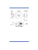
Laser Safety • • SV100C; IEC Class 3, CDRH Class III All other SV models; IEC Class 2, CDRH Class II Enclosure Description
Table of Contents Chapter 1 - Quick Check SV Series Introduction........................................................................... 1-1 SV Series Model Specifications .......................................... 1-2 ScanView Software .............................................................. 1-2 Laser Beam ........................................................................... 1-2 Chapter 2 - Control Panel Reset Button..........................................................................
PC Communication Port Setup............................................. 4-2 Software Operation Warnings .............................................. 4-3 Title Bar – Screen Display.................................................... 4-3 Menu Bar – Screen Display.................................................. 4-3 File Menu ....................................................................... 4-3 Setup Menu .................................................................... 4-3 Advanced Menu .........
Output Port Setup Commands – P ...................................... 6-19 System Control Commands – S .......................................... 6-24 How to Set Up Single Scan Operation ......................... 6-25 Checking SV Status with ~HT ..................................... 6-25 Output Interface Modes Descriptions ................................. 6-30 Mode 00 (~LV00)......................................................... 6-30 Mode 01 (~LV01).......................................................
Technical Assistance ............................................................ 9-1 Online Technical Assistance .......................................... 9-2 For Further Information ................................................. 9-2 Product Service and Repair .................................................. 9-2 Online Product Service and Repair Assistance.............. 9-3 Limited Warranty..................................................................
1 Quick Check SV Series Introduction The Hand Held Products SV Series of Scanner/Verifiers is a universal system component that analyzes linear bar code print quality, checks encoded data, and detects system failures. In its basic mode of operation, an SV unit acts similar to a normal fixed position scanner by automatically decoding bar codes as they pass through its laser beam. Additional capabilities, such as performing bar code verification and operating in synchronous modes make the SV Series unique.
SV Series Model Specifications Contact Hand Held Products Technical Support for information on custom and other models. SV100 SV100HD SV100C SV200-1 SV200-2 Analyses/ sec 100 100 100 200 200 Scan Width 6” (152mm) 4.5” (114mm) 10.5” (267mm) 2.5” (63.5mm) 1.75” (44mm) Focus Distance 8” (203mm) 6” (152mm) 15” (381mm) 8” (203mm) 6” (152mm) X dim (min) .0067” (.17mm) .005” (.127mm) .013” (.33mm) .0067” (.17mm) .005” (.
2 Control Panel The control panel displays the reset button, I/O connector, system LEDs, and the serial port connector. Reset Button The Reset button is multifunctional. It may be used to turn off the laser beam, perform calibration, and reset the ports. Turn Off Laser Beam The laser beam may be turned off (therefore turning off the SV unit’s operation) by holding down the Reset button for a few seconds until the beam turns off. Pressing the Reset button again will begin normal operation.
9 10 11 12 13 14 15 - Reserved Reserved GND +5 VDC power in Power GND GND Output Port 5 + 5 VDC Power Input The SV Series requires + 5 Volts DC, +/- 0.25 Volt. Maximum current consumption is 1 amp. The voltage input must be connected to pin 12 and the ground input should be connected to pin 13 on the I/O connector.
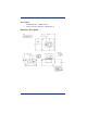
+ 5 VDC (SV PSU) 100K Ohm Pin 4 To SV sync logic TTL Sync Input Diagram SYNC To SV sync logic 6 3 D11 D19 4 2 1 Pin 2 ISO1 MOC211 5 8 VC080514A650 7 1 2 1N914 3.9 K ohm To SV sync logic Pin 1 Isolated Sync Input Diagram Sync inputs are also available via serial communications. See ~SK# (page 6-26) command for details. Hardware sync operation is very flexible due to programmable options. Two sync modes, edge and envelope, are available. Signal input polarity is also user programmable.
Edge Sync Mode This mode senses a signal transition level of a sync signal as shown below. Sync sensed here The illustration above shows the sync operation of an SV unit programmed to sense the rising edge of a sync signal in edge mode. Each time a rising edge is sensed, the SV unit does the following: 1. It verifies that at least the number of bar codes expected (programmed) since receiving the last sync input have been fully decoded.
3. Counting ceases upon receipt of the trailing edge of a sync signal. The SV Series determines that at least the number of bar codes expected (programmed) during the sync period have been fully decoded. If not, an internal No Read condition is set for possible reporting through communication or output activation. 4. The SV unit then waits for the next leading edge of a sync signal to begin counting codes being scanned and analyzed.
System Displays Five LEDs are included on the SV Series back panel. Power/Sync LED This LED is illuminated green whenever power is applied to the SV Series. Upon receipt of any sync input (hardware or serial communications), the LED blinks yellow for approximately 100 milliseconds. Calibration LED This yellow LED indicates calibration status. Please refer to "Calibration" on page 5-8 for details. Read LED This green LED is illuminated whenever a bar code is being fully decoded.
3 Serial Port Connector The serial port connector is used to interface the SV Series with devices incorporating RS-232C signal levels. The connector is a DB 9 male. The serial port can be used for reporting bar code analysis results to a host and receiving SV Command Language instruction from a host.
Legal values for each parameter are: Pos Chars Y 1 1 a 2 1 b 3 2 c 5 2 d 7 2 e 9 2 f 11 2 g 13 2 h 15 2 i 17 2 j 19 2 k 21 2 l 23 1 m 24 2 n 26 1 o 27 2 3-2 Parameters Programmable ASCII character indicates start of transmit: See ~SSbbbeee (page 6-28) command. CR (carriage return) required for ScanView. P=PASS Ref Decode, F=FAIL per Ref Decode algorithm. P and F are a majority decision over all scans. 00-9A (0-100); Decodability calc. avg.
Pos Chars p 29 1 q 30 2 r 32 1 s 33 2 t 35 3 u 38 2 v 40 1 w 41 3 x P 44 48 4 4 y* 52 2 M* 54 1 N 55 1 z 56 4 A 60 4 B 64 3 Parameters + or - indicating sign of avg. max. bar deviation calculation. + indicates wide bars. Maximum bar deviation calculation averaged over all decoded scans. Units are in % of X. Value: 00-9A (signify 0 – 100) One character: Pass(P) or Fail(F). Quiet Zone. Pass requires approximately 80% min.
Pos Chars C 67 3 D 70 3 E 73 2 F 75 2 G 77 1 H 78 2 I 80 2 J 82 2 O 84 1 K 85 1 L 86 2 [chars] 88 ... Z last 1 Parameters Three digit number shows total scans-oncode. 000-999; Good Quiet Zones (scans) Two digit number shows Lead QZ. Units: .1X (00-9A) Two digit number shows Trail QZ. Units: .1X (00-9A) One digit number: ‘0’ (off), ‘1’ (on). Sync state. IGC, two bytes: Units of X dimension times 10. Value = 00 when N/A Two digits; Percent of good global thresholds.
Identifiers Symbology Category 05 Code 3 of 9 06 Codabar 11 UPC-A 15 UPC-A w/add-on (2) 19 UPC-A w/add-on (5) 12 EAN-13 16 EAN-13 w/add-on (2) 20 EAN-13 w/add-on (5) 13 EAN-8 17 EAN-8 w/add-on (2) 21 EAN-8 w/add-on (5) 14 UPC-E 18 UPC-E w/add-on (2) 22 UPC-E w/add-on (5) Quick Check® SV Series User’s Guide 3-5
3-6 Quick Check® SV Series User’s Guide
4 ScanView Installation and Setup Introduction ScanView is designed to be a tool used for system setup and real-time bar code monitoring of a Hand Held Products SV type scanner/verifier. It is a Windows 2000/XP application with facilities for sending commands to the SV scanner/ verifier and receiving the responses. The program can view bar code analysis results and monitor bar code printing/monitoring sessions.
and follow the displayed instructions. If the previous version of ScanView was 2.07 or earlier, delete the folder that contains the remaining ScanView files: ‘c:/Program Files/Hand Held Products/ ScanView by Hand Held Products.’ Note: If you are using a CD-ROM, insert the CD and the system walks you through the set up. If you are using 3.5 diskettes, follow the steps below. Follow these steps to install ScanView: 1. Insert ScanView Installation Diskette #1 into a floppy disk drive; e.g., drive A. 2.
Software Operation Warnings Do not let other Windows applications run concurrently with ScanView. ScanView operation depends on communication and timing issues that can be disrupted when ScanView shares Windows resources with other applications. The resource sharing problem can include conflicts with Windows screensavers. ScanView blocks screensaver operation. This version of ScanView limits the number of processed bar codes to 30,700 per session.
Select Symbologies This item allows the user to program the SV unit to enable/disable individual symbology decoders. This is useful for either more secure decoding or sometimes faster throughput if a single symbology type is always being analyzed. Select Com Port This item allows the user to select a com port in the host PC. Change Verifier Baud Rate This item allows the user to program the SV scanner/verifier baud rate.
Note: In cases where the SV is scanning stationary bar codes, the “picket fence” direction must be used. Advanced Menu This menu is an extension of the Setup Menu, providing less commonly used, but useful SV system features. Toggle Display Updating This item enables/disables display updates in real time. Disallowing updates is useful to allow ScanView to keep up with a high throughput application.
Speed Button Bar – Screen Display See "Bar Code Analysis Screen" on page 4-9. The buttons on this bar give quick access to various application modes and features. All Data Points, Last 64 Data Points , Toggles the “all data points” mode and the ‘last 64 data points” mode. In the ‘last 64 data points” mode, the Graph Display Area (see "Bar Code Analysis Screen" on page 4-9) is updated immediately as the SV scanner/verifier processes each bar code.
Transmit SV Commands This button invokes a special screen where up to fourteen individual commands may be composed and transmitted in any order. Proper use requires knowledge of the SV download language. See the Chapter 6, SV Download Language for details. This function is intended for advanced setup involving special functions not normally accessed by ScanView.
exceeds the application’s processing limit it will lag farther and farther behind until the buffer overflows and the communications port ceases to operate. If this condition occurs, port operation can be restored by clicking the Initialize Com Port item in the Support Menu list. When using ScanView to monitor a printing session, the user can test for processing lag during short sample runs by intermittently blocking the beam path and noting the resulting analysis graph update lag.
Various points on the screen are marked with numbered and lettered references. Lettered references apply to ScanView screens in general. The numbered references apply to this screen in particular. Descriptions for each point are included.
Bar Code Analysis Results for a Previous Bar Code This is an example of reviewing a bar code other than the last one processed as described in the Bottom Panel explanation above. A vertical line appears while dragging the mouse with the left mouse button held down. Analysis results are shown for the column of dots (the bar code) nearest the vertical line. For example, the Bar Code Analysis Screen above exhibits the analysis results for 31st bar code in the session.
Color Coding Color Coding is an important feature of the ScanView presentation scheme. If you look at your monitor, you can see that the display contains different colors. Medium blue, light blue, yellow, magenta and red indicate ISO method bar code parameter grades A(4), B(3), C(2), D(1) and F(0), respectively. Each dot is color coded to show the grade for that particular parameter for that particular bar code. Color/Grade Reference Chart Dot indicates the ISO grade value of a bar code.
Reflectance Profile Screen This high reflectance spans includes one of the bar code quiet zones. This high reflectance spans includes one of the bar code quiet zones. In this case, the bar code segment of the profile is centered in the display; therefore it is centered in the beam path. The amplitude of the bar code signal is in the desired location between the yellow lines (10% and 90% of dynamic range) path.
5 Scanner Setup Scanner positioning and proper system setup are extremely important for proper SV Series operation. The following sections describe the most common setup possibilities in detail. Some knowledge of SV Series operation is recommended to best follow the steps. Please refer to Appendix A (SV Series Setup Hints Scanning Distance and Angle) for a basic description of SV Series operation and scanner positioning and calibration. Positioning is important to provide accurate analyses.
Scanner Positioning Each SV Series has an attached label that indicates the type of scanner, focus distance and recommended scan angle. Use the scan distance and scan angle information in the following illustration to mount the scanner. Scan Distance Laser Beam Scan Angle Beam Intersects Bar Code Here Notes: 1. Scan distance is measured from the protruding edge of the face of the scanner. 2. Scan angle is measured in degrees relative to vertical from the surface of the bar code. 3.
Bar Code Travel Direction Bar codes can be scanned in a static location, or more commonly with on-line scanner/verifiers, they can be scanned while moving through the laser beam. The illustration below shows the two directions a bar code can travel through the laser beam. They are designated “picket fence” and “ladder” directions. Picket Fence Travel Laser Beam Direction Ladder Travel Direction The SV unit must be programmed for the direction of travel of the codes being analyzed.
1. Mount the SV units at the proper distance and angle. Use "Good Reflectance Profile" on page 5-6 as a reference. 2. Connect the power and communication cables to SV unit. 3. Set the SV unit for picket fence bar code travel direction by clicking the Picket Fence Mode item in the ScanView Setup Menu. 4. Place a sample bar code in the center of the intended laser beam path. For best results, this sample should match the type of bar code(s) and material that is to be analyzed in the final application.
9. Program the SV unit’s ports, LEDs, sync mode, etc. (if required). 10. Calibrate the SV unit if any reflectance parameters (such as symbol contrast) are programmed in this application to report to a host or activate any ports. Each SV unit is supplied with a calibration symbol. 11. The SV scanner/verifier is now ready to operate for picket fence bar code travel direction.
**This procedure assumes the SV unit is mounted as shown below with the protruding surface up and the user is looking at the beam from behind the SV100. In this orientation, the beam is sweeping from left to right. Refer to "Scanner Setup" on page 5-1.
Bad Reflectance Profile Bar code signal amplitude out of range; above yellow line and also off the graph. Bar code low reflectance points not in straight, consistent values. Picket Fence Direction In picket fence travel direction, a bar code is in the laser beam throughout the height of the shortest bar in the code.
Note: If using ~HO2, ensure the bar codes with short vertical gap are encoded with different data and only one code across is being analyzed in each scan. Note: The slower of the two print speeds calculated above for bar height and gap height is the maximum recommended speed for picket fence travel. Picket Fence Bar Code Positioning Specifications: • Four codes across maximum • Horizontal gap between codes: .
Procedure 1 1. Remove all bar codes from the laser beam path. 2. Place the supplied calibration symbol in the laser beam in the same position (distance and angle) as the labels to be verified will be scanned. 3. Press and hold the RESET button on the SV unit until the Calibration LED begins to flash. 4. Release the RESET button immediately after the Calibration LED begins flashing. If calibration is successful, the laser beam will go off and the Calibration LED will go off. 5.
Adjusting Scanner Gain and Offset Scanner gain and offset adjustment via commands is available in SV units that have the “A” circled on the label that indicates focus distance. The adjustment capability is useful for adapting the unit to various material types and scanning angles during the setup procedure. Knowledge of Hand Held Products’ ScanView software is required for best understanding of the following description.
Desired Signal Amplitude and Placement • Bar code signal amplitude at least 6 lines high. (A more preferred 7 lines high is shown in this example.
5 - 12 Quick Check® SV Series User’s Guide
6 SV Command Language Introduction All commands to the verifier begin with a tilde, ‘~’, followed by one or more alphanumeric characters. The ‘~’ identifies the subsequent character string as a verifier command. The string is parsed from left to right. The first character after the ‘~’ identifies the command category. Each command requires at least one additional character that identifies the particular command from that category. Some commands require additional data, e.g.
~BCa##bc{…bbb…}{…mmm…}{…bbb…}… {etc. up to 32 characters max.} Check for specific data This command sets (enables) or clears (disables) one of 10 available data match arrays. All ten arrays may be active simultaneously. A data match error occurs if at least one array is active and the data scanned does not match the data programmed in the array. Each array can be up to 32 characters in length. Multiple portions of each array can be masked and the mask character is defined in the command.
Note: Other Data Match Fields and Fill characters can follow for up to 32 characters total length. Examples ~BC005xfABCDE Data match array #0 with 5 characters of “ABCDE” of fixed length with ‘x’ as the ignore or fill character. In this case, the ‘x’ must be in the command, but is not used ~BC210xfxxxABCDExZ Data match array #2 with 10 characters of fixed length. ‘x’ as the ignore or fill character.
bb Number of characters in array. A value of 00 clears (disables) this array. ...!!! Mask characters for defining positions in the data field not being checked. ...+++ Characters in the data field being checked. If + characters are used, this marks the field and defines its size. Maximum field lengths are 8 characters for numeric and 6 characters for alphanumeric.
If ~BU1 set, if a right bracket character ( ] ) character is set in the ~BC command data field, that will be used as a match for a Code 128 F1 character. The F1 character will be treated as a data character rather than a symbol character and therefore be included in the data match logic.
Example return using ScanView: Scan Rate: 400 ~DN# Inquire port activation data. This command instructs the verifier to report all parameters of the event that caused this port to go active. # = 1 through 8 (port ID) ~DV Inquire firmware version. 1. Commands the verifier to transmit the SV Series firmware version to the host in the following data packet format: 2. ~D 3. hexadecimal value ‘4’ - identifies the beginning of the data packet response 4.
Possible values for # are: 1 specifies 9600 2 specifies 19200 3 specifies 38400 4 specifies 57600 5 specifies 115200 the default The default value is set at the factory (before shipping). Returns the following sequence: 1. ~H 2. hexadecimal value ‘4’ - identifies the beginning of the data packet response. 3. Six hexadecimal digits (upper case) - the memory address 4. \r - carriage return character 5. \n - line feed character 6.
1 (moving bar codes mode) Use for normal operation 2 (moving bar codes mode, fast code exit) 3 (reserved) 4 (stationary bar codes mode) ~HQ# Transmission Mode Values for # are: 0 Standard mode 1-9 reserved ~HT Display the verifier parameters The format of the reply is, when ~De0 is set: (See ~De# (page 6-6) command for an alternate reply choice). 1. ~H 2. hexadecimal value ‘4’ - identifies the beginning of the data packet response. 3. A list of text strings like the one shown in the example.
[~Sl##]= 000 [c]SCfact= 045 [c]min cal= 024 [~HB#]baud= 005 [~LL]smt_decode= 471 [~LM##]chars= 032 [~LN##]num_bc= 001 [~LZ##]num_bc_exact= 000 [~LR#]No_Read_Enable=000 [~LF##] I25_Mod10_Chk=040 [~HQ#]output_mode= 000 [~HO#]oper_mode= 001 [~LA##]ansi= 000 [~LS##]min_scn= 002 [~LT#]sync_in= 001 [~LP#]sync_pol= 001 [~LX#]sync_typ= 002 [~LV##]sync_md= 001 [~PO#]port_sel= 005 [PC#]port_clear_md= 000 [Pt##]port_time= 099 [~LD##] %dec= 000 [~PR####]PRST= 000200 [~HL#]ladder_code= 000 [~HJ####]ladd_start= 0800 [~HK
[~SN###]#scans= 050 [~Lp#]part= 000 [~Lt#]itfp= 001 [DACs]= 175 156 255 255 [~LQ#]p_out= 000 [~Lw,d]def= 000 000 [~L*]pnet= 000 [~LC##]I25min= 002 [~H###]NTrys= 010 [~OS#]Data_Output= 000 [~Hs#]RunSpeed= 000 [~SS######]CntlChars=01 3 010 {hex 5} T ~Hdx01nnn Sets scanner gain or offset. x = value of 1 or 2. If =1, scanner gain is set. If = 2, scanner offset is set. nnn = gain or offset setting. For gain, the higher the value, the higher the gain. 225 is the max allowed value.
~H#nn Sets the number of signal transitions to search for finding a bar code symbol nn = values of 10 through 99. This indicates the number of high to low transitions of the optical signal to search before ending a search for a bar code. High values of nn are useful when complex graphic fields or small fonts are closely adjacent to a bar code and therefore in the scan path. The higher the number, however, the greater chance the analysis rate will be lowered.
~LE# Exclude the Specified Symbology for a Label: (‘#’ identifies the excluded symbology: Values for # are: 1 UPC/EAN 2 Code 39 3 Code 128 4 Interleaved 2 of 5 5 Code 93 6 Codabar ~LFxy Analyze special subsymbology parameters This command enables special subsymbology parameters within a symbology. This does not affect the automatic calculations and analyses for mandatory symbology check digits such as those required in Code 128, UPC/EAN and Code 93.
~LI# Include the specified symbology for a label ‘#’ identifies the included symbology: 1 UPC/EAN 2 Code 39 3 Code 128 4 Interleaved 2 of 5 5 Code 93 6 Codabar ~LL Report the excluded symbologies and the included symbologies specified for all the defined bar codes.
~LN## Set Minimum Number of Bar Codes Per Label (i.e., per sync period) This command instructs the verifier on how many bar codes it is expected to read and analyze during a sync period. If the programmed number of codes are not read, a (robust) NO READ condition is internally flagged for communications or output port activation. Except for mode ~LV03, this command sets the minimum bar codes expected. Mode ~LV03 uses this value for the EXACT number of codes read during the sync interval.
~LQ# Enable or Disable Port Activations by Partial Decodes 0 Disable Port Activation by Partial Decodes 1 Enable Port Activation by Partial Decodes ~LR# Enable or Disable No Read Transmission or Alternate Data Transmission Formats A No Read transmission message can be sent via the serial port if the SV unit is receiving sync inputs. See "Serial Port Transmission Format" on page 3-1 for details. Fields y, M and N (data positions 52 through 55) set to 0, indicate a No Read condition.
# = 6, causes the SV unit to transmit bar code data only, without the 88 byte field used to indicate all quality parameters. The data has no framing. The data format is determined by the state of the ~OS# command (data or all symbol characters). ~SA and ~SY will cause a "normal" transmission including the 88 byte field of verification analyses if a bar code is in the laser beam when the command is received. This allows bar codes to be reported to ScanView during setup.
~LV## Output Interface Mode ## = 00 - 99: This command sets the output interface mode of the unit. Modes have fixed port activation logic defined by specific applications. Some activation parameters are programmable. Custom modes are available – contact Hand Held Products Technical Support. Modes included in standard SV Series are described in the "Output Interface Modes Descriptions" on page 6-30. Example: ~LV01 sets mode 01.
~Lt# Turn partials on and off at the decoder level for Interleaved 2 of 5 codes only. 0 Disable 1 Enable Output Mode Selection Commands – O A ‘~’ followed by an ‘O’ specifies a command from the Output Mode Selection category. These commands include one additional character that identifies the particular Output Mode Command. The Output Mode Selection Commands are listed below. ~OL## Set an LED on/off.
Output Port Setup Commands – P A ’~’ immediately followed by a ‘P’ specifies a command from the Output Port Setup category. Note: The following descriptions of the ~PB and ~PP commands imply all ports are individually programmable. All SV port logic is currently programmed via the Output Interface Mode command ~LV##. See "Output Interface Modes Descriptions" on page 6-30 for details of port logic.
Table of Analysis Parameters IDs Analysis Parameters Low High Units Low Value High Value 04 Symbol Contrast 0 100 % 000 100 05 EC min 0 100 % 000 100 06 Defects 0 100 % 000 100 07 Rmin/Rmax 0 100 % 000 100 08 Rw 0 100 % 000 100 09 Rb 0 100 % 000 100 10 PCS 0 100 % 000 100 11 Z within TOL of VAL 1 255 Mils 001 255 12 AVG BWD -100 100 % of X 000* 200* 13 MIN BWD -100 100 % of X 000* 200* 14 MAX BWD -100 100 % of X 000* 200* 15
Table of Analysis Parameters Analysis Parameters IDs Low High Units Low Value High Value 22 Ref. Decode NA NA Flag 000 001 23 Character Format NA NA Flag 000 001 24 Partial Decode NA NA Flag 000 001 25 Data Match NA NA Flag 000 001 26 Illegal Position NA NA Flag 000 001 * The data format for negative numbers ranging from -100 to -1 is 0 to 99. for example, -100=0; -95=5; -10=90; 0=100; 25=125; 95=195; 100=200. ~PPpiiaaa Port action parameters.
~PLpii List all Port setup parameters. (Parameters are set by the ~PB command.) pii= Three decimal digits representing: Port- p ID- ii ~PT# Show status and all the Port Parameters (Parameters are set by the ~PB command.) Transmission is in the following format for command ~PT1: 1. ~PT 2. hexadecimal value ‘4’ - identifies the beginning of the data packet response. 3. A list of text strings like the one shown in the example.
013 - 255 255 014 - 255 255 015 - 018 000 016 - 050 100 017 - 255 255 018 - 255 255 019 - 255 255 020 - 255 255 021 - 255 255 022 - 255 255 023 - 255 255 024 - 255 255 025 - 255 255 026 - 255 255 ~PR#### Port/LED reset state #### = four hexadecimal digits Each port and led are represented by a binary digit in the four hexadecimal digits as follows: Indicator Digit Value Power Indicator 0x0001 Read LED 0x0002 LED1 0x0004 LED2 0x0008 Port 1 0x0010 Port 2 0x0020 Port 3 0x0040 Port 4 0x0080 Po
Indicator Digit Value *Sync Indicator 0x0200 *Inverted logic Except for the sync indicator, if a bit is clear, the inactive state of the port is OFF. For example: ~PR0210 = sync indicator goes “ON” when a sync is detected and Port 1 goes “OFF” when activated. All other ports go “ON” when activated. ~Px Save the new port configuration by writing it onto the flash. ~PY Cancel the current port setup (restore the old Port configuration by getting the old values from the flash).
The major trade-off to the single scan feature is only one bar code at a time can be analyzed in the beam vs. up to 4 codes in picket fence mode in the standard system. The major disadvantage to this method in cases where only a single scan is used for evaluation of a bar code is there is a higher probability that the analyses may not be accurate because part of the scan could be at the upper or lower edges of one or more of the elements in the code.
When using ScanView menus to program SV parameters, set ~De0 for normal ~HT reply or an error message may be displayed. ~SC Execute the calibration procedure. The SV unit responds to this command as follows: CP505050 is transmitted if the calibration is successful. CF000000 is transmitted if the calibration was unsuccessful ~Sc (lowercase c) Set Scanner Gain and Offset for symbol that is in the laser beam This command automatically sets the scanner gain and offset to a bar code that is in the laser beam.
4. Receipt of ~SK# command will be identical to detecting a hardware sync input 5. After receiving the ~SK# command, the SV unit will operate per settings of the various commands related to sync inputs - ~LR#, ~LV# 6. ~LP0 must be set when using any Output Interface Mode except 2 and 19 7. ~LP1 must be set if using Output Interface Mode 2 or 19 8. ~LX0, ~LX1, ~LX2 or ~LX3 can be used with any Output Interface Mode except 2 and 19 9.
~SR Reset the System. This re-initialization procedure recalls all of the current setup parameters from the flash. ~SSbbbeee Program the start and end characters in a transmission bbb = decimal value of the ASCII character that indicates the beginning of a transmission. eee = decimal value of the ASCII character that indicates the end of a transmission. Allowed values for bbb and eee are 001 through 127.
y = number of characters in the trailer. Allowed values are 0,1,2 therefore up to two trailer characters are available. If either x or y are not 0, then additional 3 digit fields indicating the decimal value of the ASCII character transmitted must be added to the command for each character placement indicated by the x and y settings. Allowed values are 001 through 255. If both x and y are 0, then the ~SS command settings are used for header and trailer characters.
~Stx Program Command Indicator Header This command programs the indicator character from a pre-determined set of available characters. x - the value of this character is used for selecting the command indicator. Available indicators are ASCII characters that are not part of any standard SV command syntax in order to be secure. Allowed values of x are 0,1, ..9.
Mode 01 (~LV01) Mode 01 I/O operation 1. System will operate in Edge Sync or Envelope sync mode (~LX#) 2. Sync polarity programmable (~LP#) 3. Use ~PR0210 for proper port initialization. 4. Port 1 will go active OFF (no current) on an error condition. 5. Port 2 will go active ON (sink current) on an error condition. 6. Pushing the reset button or power re-cycle will place Ports 1 and 2 in their inactive states and reset the # codes per sync counter. 7. Error conditions available are: a.
Note: Both LEDs can be on in cases where multiple bar codes are analyzed in a sync period. SV Commands Important to Mode 01 This system is operating in a “mode” rather than fully programmable logic. The port activation parameters are programmable via the ~PB8 rather than ~PB1, ~PB2, etc. for each individual port. Other commands, such as mode commands are also available. The commands most useful for this system application are described below. ~LV01 This command sets this mode of operation.
~PB802xxx100 This command sets the threshold for the ISO Decodability calculation on a code to set a failure condition. The field xxx is the passing threshold for the calculation. For example: if xxx = 037, a Decodability analysis of 36% or lower will cause a failure condition for this parameter. ~PB804xxx100 This command sets the threshold for the ISO Symbol Contrast calculation on a code to set a failure condition. The field xxx is the passing threshold for the calculation.
c. Overall ISO Grade (Programmable, ~LAxx) d. Bad quiet zone (~PB816xxx000) e. No Read (if sync is received) f. Partial decodes and % decode logic programmable (~Lp#, ~Lq#) g. Number of codes per sync programmable (~LN##, ~LZ##) h. Symbology modulo check digit 3. Sync polarity - Leading edge high going; time between trailing (low going) edge to leading edge - 12.5 milliseconds minimum 4. Port 1; acts as strobe (signal ensuring Port 3 condition is stable) in response to trailing edge of sync input.
~LQ0 This command disables partial decodes to activate output ports Note: In SV firmware versions x238 and lower, ~LQ commands are not implemented and the command ~HQ1 must be used to disable partial decodes from activating ports. In this case the standard data transmission format is modified and ScanView will not display data characters correctly. ~LDxx This command sets the % decode threshold for a passing condition.
This command overrides the ~LN## command if the number of codes set does not = 00. If ~LZ## is set to ~LZ00, the ~LN## command takes precedence. ~Hx This command stores all parameters into non-volatile memory. This command should be the last command sent after parameters are programmed via the above commands. Mode 03 (~LV03) This mode is identical to Mode 01 with the exception of the meaning of the ~LN command: ~LN## This command sets the exact number of codes to be read during a sync period.
d. ISO Defects grade programmable (~PB806xxx000) e. ISO Decodability grade programmable (~PB802xxx100) f. Symbol Contrast grade programmable (~PB804xxx100) g. No Read (if edge sync is received) h. Number of codes per sync programmable (~LN##, ~LZ##) i. Overall ISO Grade (Programmable, ~LAxx) j. Symbology modulo check digit Mode 12 LED Operation 1. LED1 will turn on if Ports 1-4 go active due to ISO, contrast, or quiet zone failure 2.
Note: In SV firmware versions x238 and lower, ~LQ commands are not implemented and the command ~HQ1 must be used to disable partial decodes from activating ports. In this case, the standard data transmission format is modified, and ScanView will not display data characters correctly. ~LDxx This command sets the % decode threshold for a passing condition. If analyzing poorly printed symbols, it is recommended that partial decodes be enabled at the decoder level when this command is enabled.
~LAxx This command sets the passing threshold for the Overall ISO method Symbol Grade. For example: ~LA28 causes an Overall Symbol Grade of 2.7 or lower calculated for the code analyzed to set a failure condition for this parameter. ~Hx This command stores all parameters into non-volatile memory. This command should be the last command sent after parameters are programmed via the above commands. Mode 16 (~LV16) Mode 16 I/O operation 1. System will operate in Edge Sync or Envelope sync mode (~LX#). 2.
j. X dimension (Programmable ~PB811xxxyyy) k. Symbology modulo check digit Mode 16 LED Operation 1. LED1 will turn on during the time a Port goes active due to any bar code quality or dimensional error. 2. LED2 will turn on during the time a Port goes active due to a partial or no read condition Note: Both LEDs can be on in cases where multiple bar codes are analyzed in a sync period. SV Commands Important to Mode 16 This system is operating in a “mode” rather than fully programmable logic.
~PB816xxx100 This command sets the minimum percent of scans on a code which calculate good quiet zones to determine an acceptable quiet zone analysis. The field xxx is the minimum passing threshold. Example: if xxx = 030, a minimum of 30% of all fully decoded scans on a code must calculate a good quiet zone, or a failure condition is set for this parameter. ~PB806xxx000 This command sets the threshold for the ISO Defects calculation on a code to set a failure condition.
~Hx This command stores all parameters into non-volatile memory. This command should be the last command sent after parameters are programmed via the above commands. Mode 17 (~LV17) I/O operation 1. System will operate in Edge Sync or Envelope sync mode (~LX#). 2. Sync polarity programmable (~LP#) 3. Use ~PR0200 for proper port initialization. 4. Port 1 will pulse active ON for a bar code quality or data error condition. 5. Port 2 will pulse active ON for a NO READ, partial or low % decode error condition.
m. I 2 of 5 optional Mod 10 Check Digit data error (if enabled) n. Data Match Error (~BC). o. Increment or Decrement data Error (~Br). LED Operation 1. LED1 will turn on when Port 1 is active due to ISO, Symbol Contrast, X dimension, ratio, mod check or quiet zone error conditions. 2. LED1 will flash when Port 1 is active due to a data increment or decrement error condition. 3. LED2 will turn on when Port 2 is active due to a partial, % decode or no read error conditions. 4.
~LDxx This command sets the % decode threshold for a passing condition. If analyzing poorly printed symbols, it is recommended that partial decodes be enabled at the decoder level when this command is enabled. xx = failure threshold. Example ~LD75: if 74 % or less of scans on a code were not fully decoded, this sets a failure for this parameter. ~PP801xxx This command sets the “active” time for the port pulses. The value “xxx” sets the time in .1 second intervals.
~LN## This command sets the minimum number of codes to be read during a sync period. ## = the number of codes. For example: ~LN02 causes a No Read condition to be set if less than 2 bar codes are fully decoded during a sync interval. See the ~LZ## (page 6-17) command below for priority. If the value ## = 00 (and ~LZ00 is also set), a sync input is disregarded, therefore a No Read condition is disabled. ~LZ## This command sets the exact number of codes to be read during a sync period.
11. Error conditions available are: a. Partial Read (Programmable, ( ~Lp#, LQ#) b. % decode (Programmable, ~LD##) c. Bad Quiet Zone: < 10X (~PB816xxx100) d. ISO Defects grade (Programmable, ~PB806xxx000) e. ISO Decodability grade (Programmable, ~PB802xxx100) f. Symbol Contrast grade (Programmable, ~PB804xxx100) g. Overall ISO Grade (Programmable, ~LAxx) h. No Read (if sync is received) i. Number of codes per sync programmable (~LN##, ~LZ##) j. X dimension Range (Programmable ~PB811xxxyyy) k.
SV Commands Important for Mode 18 This system is operating in a “mode” rather than fully programmable logic. The port activation parameters are programmable via the ~PB8 rather than ~PB1, ~PB2, etc. for each individual port. Other commands, such as mode commands are also available. The commands most useful for this system application are described below. ~LV18 This command sets this mode of operation.
~PB806xxx000 This command sets the threshold for the ISO Defects calculation on a code to set a failure condition. The field xxx is the passing threshold for the calculation. For example: if xxx = 025, a Defects analysis of 26% or higher will cause a failure condition for this parameter. ~PB802xxx100 This command sets the threshold for the ISO Decodability calculation on a code to set a failure condition. The field xxx is the passing threshold for the calculation.
~Hx This command stores all parameters into non-volatile memory. This command should be the last command sent after parameters are programmed via the above commands. Mode 19 (~LV19) I/O operation 1. Envelope type sync input on pin 4 2. Port 3: per sync type. The state of this output must be stable within 12.5 milliseconds after the sync input goes low (trailing edge.) Typical time for stability will be less than 7.5 milliseconds if the sync is received when a bar code or complex graphic is not in the beam.
5. Ports 1 and 3 will go high (no current) within 12.5 milliseconds after the sync input goes high (leading edge). 6. Use ~PR0200 for proper port initialization. LED Operation 1. LED1 will turn on when Port 3 is active due to ISO, Symbol Contrast, X dimension, ratio, mod check or quiet zone error conditions. 2. LED1 will flash when Port 3 is active due to a data increment or decrement error condition. 3. LED2 will turn on when Port 3 is active due to a partial, % decode or no read error conditions. 4.
~LDxx This command sets the % decode threshold for a passing condition. If analyzing poorly printed symbols, it is recommended that partial decodes be enabled at the decoder level when this command is enabled. xx = failure threshold. Example ~LD75: if 74 % or less of scans on a code were not fully decoded, this sets a failure for this parameter. ~PB816xxx100 This command sets the minimum percent of scans on a code which calculate good quiet zones to determine an acceptable quiet zone analysis.
If the value ## = 00 (and ~LZ00 is also set), a sync input is disregarded, therefore a No Read condition is disabled. ~LZ## This command sets the exact number of codes to be read during a sync period. ## = the number of codes. For example: ~LZ02 causes a No Read condition to be set if exactly 2 bar codes are not fully decoded during a sync interval. This command overrides the ~LN## command if the number of codes set does not = 00. If ~LZ## is set to ~LZ00, the ~LN## command takes precedence.
7 ISO Parameter Grade Thresholds ISO parameter fail thresholds are set in the SV Series by commands requiring numeric settings that correlate to the parameter calculations. Following are descriptions of how the numeric calculations are divided into letter grades per the ISO Bar Code Quality Specification. Rmin Modulation A < .5 x Rmax A > .70 F > .5 x Rmax B > . 60 C > .50 D > .40 F < .40 Symbol Contrast Decodability A > 70% A > .62 B > 55% B > .50 C > 40% C > .37 D > 20% D > .
Reference Decode A = ISO method algorithm decoded the symbol F = ISO method algorithm could not decode the symbol 7-2 Quick Check® SV Series User’s Guide
8 Technical Specifications QCOLVSV Series Product Specifications Parameter Specification Physical Package 4.4” (112 mm) x 2.4” (61mm) x 5.2” (132 mm) Indications 5 LEDs - PowerSync, Calibration, Read, 2 Programmable LEDs 1 and 2 Comm Port DB-9, male, RS-232C, programmable baud rate up to 115,200 baud I/O Power DB-15, male, 5 programmable outputs, 2 sync inputs +5VDC @ 1 amp required Mounting 2 sets of mounting holes on 2 different surfaces or a clamp for tightening to 3/8” (9.
Scanning Performance–SV Series Model SV100 SV100HD SV100C SV200-1 SV200-2 Analyses/ sec 100 100 100 200 200 Scan Width 6” (152mm) 4.5” (114mm) 10.5” (267mm) 2.5” (63.5mm) 1.75” (44mm) Focus Distance 8” (203mm) 6” (152mm) 15” (381mm) 8” (203mm) 6” (152mm) X dim (min) .0067” (.17mm) .005” (.127mm) .013” (.33mm) .0067” (.17mm) .005” (.
• Sync input recovery time: 12.
Note: When in this sync mode, the sync input is a background application. The SV Series will scan, analyze and report on bar codes as they pass through the beam in this mode, regardless if a sync signal is sensed. The presence of a sync signal allows the number of codes expected (programmed) during the sync period to be used for a No Read condition. The absence of a sync signal results in operation similar to the Free Scan Operation described later.
• • • • • • • • • • • • • • • • • • • • • • Reference Decode (ISO method parameter) Decodability (ISO method parameter) Modulation (ISOISO method parameter) Defects (ISO method parameter) Edge Contrast (ISO method parameter) Rmin/Rmax (ISO method parameter) Symbol Contrast (ISO method parameter) PCS (Traditional method parameter) Reflectance – Light (Traditional method parameter) Reflectance – Dark (Traditional method parameter) Ratio (Traditional method parameter) Average Bar Deviation (Traditional method
8-6 Quick Check® SV Series User’s Guide
9 Maintenance/Customer Support Maintenance The Quick Check SV Series is designed to provide maintenance-free operation through its life and contains no moving parts that require maintenance. Repairs and/or upgrades are not to be performed on this product. These services are to be performed only by an authorized service center. Cleaning The output window should be kept clean by wiping it with a slightly dampened, soft cloth. Dampen the cloth with water or a screen cleaner.
Japan Telephone: +813 5770-6312 E-mail: aptechsupport@handheld.com Malaysia Telephone: +603-6201-7020 E-mail: aptechsupport@handheld.com Online Technical Assistance You can also access technical assistance online at www.handheld.com. For Further Information To download the full User’s Guide for these products, visit our website at www.handheld.com. Product Service and Repair Hand Held Products provides service for all its products through service centers throughout the world.
Europe, Middle East, and Africa Telephone: +31 (0) 40 2901 633 Fax: +31 (0) 40 2901 631 E-mail: euservice@handheld.com Asia Pacific Telephone: +852-2511-3050 Fax: +852-2511-3557 E-mail: apservice@handheld.com Japan Telephone: +813-5770-6312 Fax: +813-5770-6313 E-mail: apservice@handheld.com Online Product Service and Repair Assistance You can also access product service and repair assistance online at www.handheld.com. Limited Warranty Hand Held Products, Inc.
EXCEPT AS MAY BE OTHERWISE PROVIDED BY APPLICABLE LAW, THE FOREGOING WARRANTY IS IN LIEU OF ALL OTHER COVENANTS OR WARRANTIES, EITHER EXPRESSED OR IMPLIED, ORAL OR WRITTEN, INCLUDING, WITHOUT LIMITATION, ANY IMPLIED WARRANTIES OF MERCHANTABILITY OR FITNESS FOR A PARTICULAR PURPOSE. HAND HELD PRODUCTS’ RESPONSIBILITY AND PURCHASER’S EXCLUSIVE REMEDY UNDER THIS WARRANTY IS LIMITED TO THE REPAIR OR REPLACEMENT OF THE DEFECTIVE PRODUCT.
A SV Series Setup Hints - Scanning Distance and Angle Introduction The Hand Held Products SV Series of Scanner/Verifiers requires a fixed scanning distance and angle for maximum verification analysis accuracy. This is similar to the requirement of a wand "guide" on a portable bar code verifier to ensure the optics is placed at a consistent angle. If the "guide" is not placed properly, analysis results will become inaccurate, although the bar code will still be decoded.
Note: A scan distance too close will read a larger than the known X dimension. Too far will read smaller than the known dimension. The X dimension is titled "X (mils)" in the ScanView Session Mode display as shown in the figure below. Once the Scan distance (and angle --"Setting the Proper Scan Angle" on page A2) is set, the SV unit does not have to be moved again.
SV units incorporate proprietary, analog scanners. The scanner gain and offset are adjustable, allowing the units to adapt to practically any material. ScanView software allows easy setup of scanner gain and offset. A quick method of adjusting the scanner using a special command ~Sc is described below. If the "quick method" described below is unsuccessful, follow the setup procedure in ~Hdx01nnn (page 6-10) using the ~Hd commands. 1.
and offset for this material and do not use any parameters that involve reflectance measurements for failure detection for this application. See "Calibration Hints" on page A-5. Note: At this point the scanner is set up for the material in the application and the ~Sc command has been used at least once to change the scanner's setting from the initial state. 14. To finalize the settings, transmit the SV command ~Hx (lowercase x).
All of bar code signal not between yellow lines Bottom of bar code signal not “flat” Figure 3 - Examples of Scan Profile Parameters Out of Range Calibration Hints Calibration is used to normalize reflectance calculations to known (and/or traceable) values in absolute units of % reflectance. Calibration affects reflectance calculations only. Calibration does not affect any other calculations or ability to decode a symbol, etc.
A-6 Quick Check® SV Series User’s Guide
Hand Held Products, Inc. 700 Visions Drive P.O.