
Product Manual


3 Post Pressure Fit System - User Guide Rev: 2lst September, 2011 Page: 4
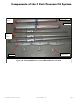
Placement of the 3 Post Pressure Fit System in a Room
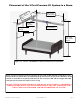
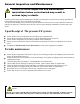
Figure 1-A shows 3 post pressure fit system set up in a room. In this drawing arrangement, a gen-
eral placement of a bed is shown in relationship to the Pressure Fit System. Notice that there is still
room for a wheelchair to be placed beside the bed. The view shows min and max height and width
of the pressure fit system for which it can be set up.
DO NOT USE THE SYSTEM OUTSIDE OF THIS RANGE OF PLACEMENT OTHERWISE A
SERIOUS INJURY MAY OCCUR TO THE OPERATOR OF THE LIFT AND/OR THE INDI-
VIDUAL BEING TRANSFERRED, AND/OR THE PRESSURE FIT SYSTEM.
MIN. 7 FEET
MAX. 10 FEET
WIDE
MIN. 7 FEET
MAX. 9 FEET
HEIGHT
MIN. 6 FEET
MAX. 8 FEET
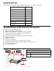
LIFT TROLLEY
SWIVEL
TROLLEY
SIDE SUPPORT
ASSEMBLY
ADJUSTABLE
TRACK
Figure 1A– FULLY ASSEMBLED 3 POST PRESSURE FIT SYSTEM