6770 STOP! Call Us First! DO NOT RETURN TO STORE. For immediate help with assembly or product information call our toll-free number: 1-888-827-9056 or email: customerservice@backyardproductsllc.com Our staff is ready to provide assistance.
(This page intentionally left blank.
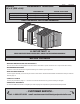
GABLE 10' x 8' (305 x 244) ASSEMBLY MANUAL BUILDING SIZE BASE MODEL ADD ONE 10' x 4' ADD TWO 10' x 4' 10' x 8' (305 x 244 cm) 10' x 12' (305 x 365,8 cm) 10' x 16' (305 x 487,7 cm) 16770 06/16/2011 ACTUAL FLOOR SIZE 10' x 7' 8-5/8" (305 x 235,3 cm) 10' x 11' 8-5/8" (305 x 357,2 cm) 10' x 15' 8-5/8" (305 x 479 cm) KEEP THIS MANUAL FOR FUTURE REFERENCE IMPORTANT! READ INSTRUCTIONS THOROUGHLY PRIOR TO BEGINNING ASSEMBLY.
TOOLS Required ❑ Phillips Screwdriver Optional ❑ Tool Belt/ Nail Pouch ❑ Utility Knife ❑ Shingle Blades ❑ Drill / Driver ❑ 3/8" Drill Bit ❑ #2 Philips Drive Bit ❑ Hammer ❑ Tin Snips (for drip edge) ❑ Caulk Gun ❑ Chalk Line ❑ Paint Tools ❑ Level ❑ Nail Gun ❑ Pencil ❑ Safety Glasses ❑ Tape Measure ❑ Ladder ❑ Square • gun nails ❑ Gloves or Safety! Always use approved safety glasses during assembly. HELPFUL REMINDER SYMBOLS Look for these symbols for helpful reminders throughout this manual.
PARTS IDENTIFICATION AND SIZES WOOD SIZE CONVERSION CHART Part identi cation is stamped on some parts. Nominal Board Size Actual Size 2" x 4"..............1-1/2" x 3-1/2" (3,8 x 8,9 cm) 1" x 4".................3/4" x 3-1/2" (1,9 x 8,9 cm) RS RS 2" x 3"..............1-1/2" x 2-1/2" (3,8 x 6,3 cm) 1" x 3".................3/4" x 2-1/2" (3,8 x 6,3 cm) • Check these locations for part stamp. 10x8' GABLE 10' X 8' PARTS LIST WALL INVENTORY YOUR PARTS before you begin.
WALL PANEL & DOORS PARTS LIST x1 x4 x1 x2 x1 x1 x1 x1 LEFT DOOR RIGHT DOOR 3/8 x 48 x 72" (1 x 122 x 183 cm) ROOF PANELS 48" x 96" (122 x 244 cm) x2 19" x 96" (48 x 244 cm) x2 Roof panels are 7/16" (11 mm) thick.
PARTS IDENTIFICATION AND SIZES WOOD SIZE CONVERSION CHART Part identi cation is stamped on some parts. Nominal Board Size Actual Size 2" x 4"..............1-1/2" x 3-1/2" (3,8 x 8,9 cm) 1" x 4".................3/4" x 3-1/2" (1,9 x 8,9 cm) RS RS 2" x 3"..............1-1/2" x 2-1/2" (3,8 x 6,3 cm) 1" x 3".................3/4" x 2-1/2" (3,8 x 6,3 cm) • Check these locations for part stamp.
ADDITIONAL MATERIALS FOUNDATION OR FLOOR MATERIALS • This shed kit does not include a wood oor frame. It does not include any oor panels. • See page 8 for the additional Áoor panel sizes and quantities required. • This shed does not include any leveling materials. • See the FLOOR LEVELING section on page 10 for recommended methods and suggested materials to properly level your Áoor, as this will vary depending on your speciÀc site.
CONCRETE FOUNDATION If you choose to install your kit on a concrete slab refer to the diagram below. Attach the sill plates on the foundaton as shown, and continue on to page 9. Treated Sill Plate Caulk between sill plate and concrete. D D C 3-1/2" (8,9 cm) B A 4" (10 cm) Sill plates MUST be treated lumber.
WOOD FLOOR FRAME (Not Included) If you choose to build a wooden Áoor system, you will need treated 2 x 4" boards cut to size and nails. Floor panel sizes and quantities are shown below. Floor Frame MUST be treated lumber. Materials shown are raw sizes and will need to be cut to size. x5 GABLE 10' x 8' x2 x3 2 x 4 x 96 (5 x 10 x 244 cm) 2 x 4 x 120" (5 x 10 x 305 cm) 48" x 96" (122 x 244 cm) 24" o.c.
INSTRUCTION MANUAL LAYOUT TABS ARE DISPLAYED AT THE OUTSIDE EGDE OF INSTRUCTION PAGES TO IDENTIFY MODEL SIZE. GABLE 10' x 8' GABLE 10' x 12' D O O R D O O R Look for this tab throughout instructions. If tab is not displayed, skip to next page including 10' x 12' tab D O O R Look for this tab throughout instructions.
OPTIONAL WOOD FRAME FLOOR LEVELING OPTIONS There are multiple ways to level your oor frame. Our recommended leveling method is shown below. Leveling materials are not included in this kit. PREFERRED METHOD - 4x4 TREATED RUNNERS (Typical for 10' x 8' Kit) Runners are generally 12" (30,5 cm) from ends of Áoor frame and under seams. Measurements to centers of 4x4's. 12" (30,5 cm) • 3" Screws angled into 4x4. • (2) at each point frame and 4x4 touch. Fig. A DOOR 12" (30,5 cm) Fig.
LEVELING & SQUARING A 10 x 8' FLOOR FRAME (Not Included) • FOR 10' x 12', SKIP TO PAGE 12 • FOR 10' x 16', SKIP TO PAGE 13. LEVEL AND SQUARE FLOOR FRAME Before attaching oor decking, it is important to level and square the oor frame. A level and square oor frame is required to correctly construct your shed. BEGIN 1 See page 10 for the preferred oor leveling method. Use level and check the frame is level before applying oor panels.
LEVELING & SQUARING A 10 x 12' FLOOR FRAME (Not Included) LEVEL AND SQUARE FLOOR FRAME Before attaching oor decking, it is important to level and square the oor frame. A level and square oor frame is required to correctly construct your shed. BEGIN See page 10 for the preferred oor leveling method. 2 Use level and check the frame is level before applying oor panels. 3 Check for frame squareness by measuring diagonally across corners. If the measurements are the same, the frame is square.
LEVELING & SQUARING A 10 x 16' FLOOR FRAME (Not Included) LEVEL AND SQUARE FLOOR FRAME Before attaching oor decking, it is important to level and square the oor frame. A level and square oor frame is required to correctly construct your shed. BEGIN 1 See page 10 for the preferred oor leveling method. Use level and check the frame is level before applying oor panels. 3 Check for frame squareness by measuring diagonally across corners. If the measurements are the same, the frame is square.
I M PIMPORTANT! ORTANT! NOTE: GABLE 10' x 8' shown standard throughout manual Check the Áoor frame is level after installing Áoor panels. Re-level if needed. OR DO • The Áoor should used as a stable work surface for wall construction. HINT: • Organize your assembly procedure during the build process to avoid over-handling of the walls.
RAFTER ASSEMBLY JIG x8 PARTS REQUIRED: 1-1/4" (3,2 cm) x2 GAA 3/4 x 3 x 5" (1,9 x 7,6 x 12,7 cm) x2 GBZ 3/4 x 3 x 8-1/2" (1,9 x 7,6 x 21,6 cm) ¸1 BEGIN Build a Jig to ensure all Rafters are assembled the same. Mark a straight line on the Floor from corner to corner (Fig. A) or on sill plates to t measurements (Fig. B). 3 Screw blocks in place to measurement shown. D O O R 2 GABLE 10' x 8' Make sure blocks are square and at 125" (317,5 cm) FINISH 4 You have nished building a Rafter Jig.
RAFTERS 10x8' 10x12' 10x16' PARTS REQUIRED: x6 x10 x14 x6 x10 x14 x72 x102 x168 6 x 24" (15 x 61 cm) CV 2 x 4 x 65-7/8" (5 x 10 x 167 cm) 2" (5 cm) • FOR 10' x 8', ASSEMBLE (3) RAFTERS TOTAL. • FOR 10' x 12', ASSEMBLE (5) RAFTERS TOTAL. GABLE 10' x 8' BEGIN • FOR 10' x 16', ASSEMBLE (7) RAFTERS TOTAL. 2 R Place two rafter halves CV on oor jig. D O O ¸1 Apply glue on gusset and place on rafters. 3 Nail gusset onto rafter using 2" nails, staggered, as shown.
BACK WALL FRAME PARTS REQUIRED: x1 x6 3" (7,6 cm) NH 2 x 3 x 46-1/4" (5 x 7,6 x 117,5 cm) PB x2 2 x 3 x 77" (5 x 7,6 x 196 cm) x1 PR 2 x 3 x 94-1/2" (5 x 7,6 x 240 cm) BEGIN Orient parts on edge on oor as shown. 2 Nail using two 3" nails at each connection.
BACK WALL FRAME x2 PARTS REQUIRED: x1 3" (7,6 cm) NH 2 x 3 x 46-1/4" (5 x 7,6 x 117,5 cm) 3 Orient parts on edge on oor as shown. 4 Use two 3" screws at middle connection. FINISH GABLE 10' x 8' 48-3/4" (124 cm) R You have nished building your back wall frame.
BACK WALL PANELS PARTS REQUIRED: x29 x1 2" (5 cm) GAA 3/4" GAUGE BLOCK 2 Use a 3/4" gauge block at edges of panel. Be sure to maintain 1" measurement between bottom edge of frame and bottom edge of panel (Fig. A, B). 3 Nail using 2" nails 6" apart on edges and 12" apart inside panel. . D O O Place LEFT panel on back frame as shown with primed side facing up. Do not nail in groove. GABLE 10' x 8' 1 R BEGIN For squareness maintain 3/4" measurement along panel edges.
BACK WALL PANELS PARTS REQUIRED: x29 2" (5 cm) x1 GAA 4 Place RIGHT panel on back frame as shown with primed side facing up. 5 Use a 3/4" gauge block at outside edge of panel. 6 Nail using 2" nails 6" apart on edges and 12" apart inside panel. 7 D O O R . Do not nail in groove. Proceed to building your wing wall panels. To draw panels tight at seams angle nail.
WING WALL PANELS x32 PARTS REQUIRED: x2 LEFT x2 RIGHT x4 1-1/4" (3 cm) OY 2 x 3 x 72" (5 x 7,6 x 183 cm) BEGIN 2 Place OY on oor. Place a wing wall panel primed side down onto OY (Fig. A) and Áush to panel edges as shown. 3 Secure ush to edges using eight 1-1/4 screws 10" apart. 4 You have nished building two sets of wing wall assemblies. Set ONE LEFT and ONE RIGHT aside. Continue building your back wall. D O O R You will assemble TWO RIGHT and TWO LEFT wing walls.
BACK WALL PANELS PARTS REQUIRED: x24 2" (5 cm) Pre-assembled x1 LEFT x1 Pre-assembled RIGHT Place wing wall assemblies onto frame with bottom of panels ush. 6 Nail left and right wing wall assemblies onto back wall frame using 2" nails 6" apart. Do not nail in groove. D O O R 5 GABLE 10' x 8' FINISH 7 You have nished attaching your wing walls. GABLE 10' x 16' GABLE 10' x 12' Primed Side UP 6" (15 cm) LEFT 3-A Flush 6" (15 cm) RIGHT HINT: To draw panels tight at seams angle nail.
FRONT WALL FRAME PARTS REQUIRED: x6 3" (7,6 cm) LT x1 2 x 3 x 22-1/8" (5 x 7,6 x 56 cm) x2 PB 2 x 3 x 77" (5 x 7,6 x 196 cm) x1 PR 2 x 3 x 94-1/2" (5 x 7,6 x 240 cm) BEGIN Lay out two PB, one PR and one LT on edge on oor. 2 Nail two PB to PR with two 3" nails at each end. 3 Ensure LT is centered with PR and nail in place with two 3" nails. FINISH 4 LT You have nished building your Front Wall Frame.
FRONT WALL PANELS x22 PARTS REQUIRED: 2" (5 cm) GAA x1 3/4" GAUGE BLOCK Place LEFT panel on front frame as shown with primed side up. 2 Use a 3/4" gauge block on edges of panel. Be sure to maintain 1" measurement between bottom edge of frame and bottom edge of panel (Fig. A). 3 Nail panel to frame with 2" nails 6" apart. R 1 Do not nail in groove. GABLE 10' x 12' 3/4" GAUGE BLOCK For squareness, maintain 3/4" measurements along panel edges. Fig.
FRONT WALL PANELS x22 PARTS REQUIRED: 2" (5 cm) GAA 3/4" GAUGE BLOCK x1 4 Place RIGHT panel on front frame primed side up. 5 Use a 3/4" gauge block on edges of panel. 6 Nail panel to frame with 2" nails 6" apart. R D O O To draw panels tight at seams angle nail. GABLE 10' x 8' Do not nail in groove. Primed Side UP GABLE 10' x 12' Panels Flush 3/4" (1,9 cm) Gauge Block 3/4" (1,9 cm) 1" (2,5 cm) For squareness, maintain 3/4" and 97-1/2" measurements.
FRONT WALL PANELS PARTS REQUIRED: x24 2" (5 cm) Pre-assembled x1 LEFT x1 Pre-assembled 7 Place wing wall panels onto frame with bottom of panels ush. 8 Nail left and right wing wall assemblies using 2" nails 6" apart. 9 R D O O You have nished attaching your wing walls. Primed Side UP 6" (15,2 cm) 6" (15,2 cm) Flush GABLE 10' x 16' Do not nail in groove. FINISH GABLE 10' x 12' GABLE 10' x 8' RIGHT To draw panels tight at seams angle nail. Use a 2x3" for support.
10' x 8' SIDE WALL FRAMES PARTS REQUIRED: x28 3" (7,6 cm) x4 7/16 x 2-1/2 x 24-3/4" (1,1 x 6,4 x 62,9 cm) x6 OV 2 x 3 x 69" (5 x 7,6 x 175 cm) x2 PM 2 x 3 x 92-5/8" (5 x 7,6 x 235,3 cm) • FOR 10' x 12', SKIP TO PAGE 31. • FOR 10' x 16', SKIP TO PAGE 35. BEGIN 2 Use two 3" nails at each mark. IMPORTANT! You will build two walls the same. D O O R Orient parts on edge on oor. Measure and mark from end of boards.
10' x 8' SIDE WALL FRAME - SOFFIT PARTS REQUIRED: x22 1-1/4" (3,2 cm) x2 3/8 x 5 x 93-1/4" (0,9 x 12,7 x 236,9 cm) 3 Place panel onto 2 x 3 with primed side against 2 x 3 (Fig A) Keep panel Áush along entire edge of 2 x 3 top plate (Fig A). D O O R Attach sof t panel ush to 2 x 3 (Fig A) and with 3/8" offset at ends (Fig. B, C) using eleven 1-1/4" screws. GABLE 10' x 8' 4 Approximate screw spacing 9-1/2" (24 cm) 3/8" (10 mm) 3/8" (10 mm) 93-1/4" (236,9 cm) Fig.
10' x 8' SIDE WALL PANELS PARTS REQUIRED: x58 2" (5 cm) GAA 3/4" GAUGE BLOCK x2 3/8 x 48 x 72" (1 x 122 x 183 cm) 5 Ensure your wall frame is square by installing one panel and squaring frame. Place the 48 x 72" panel onto wall frame with primed side up as shown. Note the lip and square edges. D O O R Use the gauge block to mark the 3/4" measurement on the wall stud. Locate the panel ush under the sof t panel. Secure panel with two 2" nails in the corners (Fig. A). Move to the opposite end.
10' x 8' SIDE WALL PANELS PARTS REQUIRED: 2" (5 cm) 3/8" x 48" x 72" (1 x 122 x 183 cm) x2 8 x58 Place 48" panel on frame as shown with primed side facing up. NOTE THE SQUARE AND LIP EDGES. Do not nail in groove. GABLE 10' x 8' D O O R Nail using 2" nails 6" apart on edges and 12" apart inside panel. Flush To draw panels tight at seams angle nail. GABLE 10' x 12' 12" (30 cm) GABLE 10' x 16' 6" (15 cm) 48" (122 cm) LIP EDGE SQUARE EDGE D O O R Carefully ip your sidewall over.
10' x 12' SIDE WALL FRAMES PARTS REQUIRED: x2 x52 NK 2 x 3 x 48" (5 x 7,6 x 122 cm) x10 7/16 x 2-1/2 x 48" (1,1 x 6,4 x 122 cm) x4 OV 7/16 x 2-1/2 x 24-3/4" (1,1 x 6,4 x 62,9 cm) 2 x 3 x 69" (5 x 7,6 x 175 cm) x2 3" (7,6 cm) x2 PM 2 x 3 x 92-5/8" (5 x 7,6 x 235,3 cm) BEGIN 1 Orient parts on edge on oor. Measure and mark from end of boards. 2 Use two 3" nails at each mark.
10' x 12' SIDE WALL FRAME - SOFFIT PARTS REQUIRED: x34 1-1/4" (3,2 cm) x2 3/8 x 5 x 48" (0,9 x 12,7 x 122 cm) x2 3/8 x 5 x 93-1/4" (0,9 x 12,7 x 236,9 cm) 3 Place panels onto 2 x 3 with primed side against 2 x 3 as shown (Fig A) Keep panel Áush along entire edge of 2 x 3 top plate (Fig A). R Attach sof t panels ush to 2 x 3 (Fig A) and with 3/8" offset at ends (Fig. B, C) using (16) 1-1/4" screws. GABLE 10' x 12' GABLE 10' x 8' D O O 4 Fig. B Fig.
10' x 12' SIDE WALL PANELS PARTS REQUIRED: x58 2" (5 cm) GAA 3/4" GAUGE BLOCK x2 3/8 x 48 x 72" (1 x 122 x 183 cm) Ensure your wall frame is square by installing one panel and squaring frame. 5 Place the 48 x 72" panel onto wall frame with primed side up as shown. Note the lip and square edges. D O O R Use the gauge block to mark the 3/4" measurement on the wall stud. Locate the panel ush under the sof t panel. Secure panel with two 2" nails in the corners (Fig. A). Move to the opposite end.
10' x 12' SIDE WALL PANELS PARTS REQUIRED: x148 2" (5 cm) 3/8" x 48" x 72" (1 x 122 x 183 cm) x4 8 Place 48" panels on frame as shown with primed side facing up. NOTE THE SQUARE AND LIP EDGES. Do not nail in groove. D O O R Nail using 2" nails 6" apart on edges and 12" apart inside panel. GABLE 10' x 8' To draw panels tight at seams angle nail.
10' x 16' SIDE WALL FRAMES PARTS REQUIRED: x72 x4 3" (7,6 cm) x4 7/16 x 2-1/2 x 48" (1,1 x 6,4 x 122 cm) x14 7/16 x 2-1/2 x 24-3/4" (1,1 x 6,4 x 62,9 cm) x2 OV 2 x 3 x 69" (5 x 7,6 x 175 cm) x2 NK 2 x 3 x 48" (5 x 7,6 x 122 cm) PM 2 x 3 x 92-5/8" (5 x 7,6 x 235,3 cm) BEGIN 1 Orient parts on edge on oor. Measure and mark from end of boards. IMPORTANT! You will build two walls the same. Use two 3" nails at each mark.
10' x 16' SIDE WALL FRAME- SOFFIT PARTS REQUIRED: x44 1-1/4" (3,2 cm) x4 3/8 x 5 x 48" (0,9 x 12,7 x 122 cm) x2 3/8 x 5 x 93-1/4" (0,9 x 12,7 x 236,9 cm) 3 Place panels onto 2 x 3 with primed side against 2 x 3 as shown (Fig A) Keep panel Áush along entire edge of 2 x 3 top plate (Fig A). O R Attach sof t panels ush to 2 x 3 (Fig A) and with 3/8" offset at ends (Fig. B, C) using nineteen 1-1/4" screws. D O GABLE 10' x 8' 4 Fig. C 3/8" (10 mm) GABLE 10' x 12' Use two screws at seam.
10' x 16' SIDE WALL PANELS PARTS REQUIRED: x58 2" (5 cm) GAA 3/4" GAUGE BLOCK x2 3/8 x 48 x 72" (1 x 122 x 183 cm) Ensure your wall frame is square by installing one panel and squaring frame. 5 Place the 48 x 72" panel onto wall frame with primed side up as shown. Note the lip and square edges. D O O R Use the gauge block to mark the 3/4" measurement on the wall stud. Locate the panel ush under the sof t panel. Secure panel with two 2" nails in the corners (Fig. A). Move to the opposite end.
10' x 16' SIDE WALL PANELS PARTS REQUIRED: x238 2" (5 cm) 3/8" x 48" x 72" (1 x 122 x 183 cm) x6 8 Place 48" panels on frame as shown with primed side facing up. NOTE THE SQUARE AND LIP EDGES. Do not nail in groove. D O O R Nail using 2" nails 6" apart on edges and 12" apart inside panel. GABLE 10' x 8' To draw panels tight at seams angle nail.
BACK WALL INSTALLATION PARTS REQUIRED (TEMPORARY): x1 x8 OO 3" (7,6 cm) x24 2 x 3 x 69" (5 x 7,6 x 175,3 cm) 2" (5 cm) BEGIN Center back wall assembly on the 120" (305 cm) oor dimension. 2 Use OO as a temporary brace. Secure with two 3" screws. R 1 D O O NOTE: 10'x8' Gable Shown. First, nail lower edge of panel to oor frame using 2" nails 6" apart. Angle nail to hit oor frame (Fig. A). GABLE 10' x 12' 4 GABLE 10' x 8' 3 ) 05 cm 120" (3 3" (7,6 cm) Screws Do not nail in groove.
SIDE WALLS INSTALLATION 10x8' 10x12' 10x16' x2 x4 x8 x12 x30 x39 x48 3" (7,6 cm) 3" (7,6 cm) 2" (5 cm) Additional fasteners needed for 10' x 12' kit or 10' x 16' kit. Same instructions apply. BEGIN D O O R Stand right sidewall on oor. It is important to secure the sidewall in the following order: GABLE 10' x 8' SofÀt Panel 1 Center sidewall on oor front to back. Rest the top of the sidewall so the sof t panel overlaps the backwall panel 3/8" (Fig. A).
FRONT WALL INSTALLATION x8 3" (7,6 cm) x36 2" (5 cm) BEGIN Stand frontwall on oor. It is important to secure the frontwall in the following order. SofÀt Panel 3/8" (0,9 cm) OVERLAP Trim Panel The sidewall sof t will overlap the frontwall 3/8" (Fig. A). R Center frontwall on oor side-to-side. D O O 1 Fig. A Nail the lower sidewall corner to the frontwall trim with one 2" nail (Fig. C). 2" (5 cm) Nail Fig. B Trim 2" (5 cm) Nail 6" 6" (15 cm) (15 cm) CENTER Fig.
GABLE TRIM x24 PARTS REQUIRED: x4 1-1/4" (3 cm) CD 2 x 3 x 54-5/16" (5 x 7,6 x 138 cm) ¸1 GABLE 10' x 8' BEGIN Position second CD ush to panel edge and ush to CD already attached (Fig. A). Attach trim with eight 1-1/4" screws from inside. Install two screws at seam (Fig. B). 3 Repeat steps 1-2 to attach the back trim. D O O 2 R Position one CD ush to front panel edge and center on right edge of groove (Fig. A). Attach trim with eight 1-1/4" screws from inside.
TRIM / ENDCAPS x32 PARTS REQUIRED: x4 1-1/4" (3,2 cm) GAA 3/4 x 3-1/2 x 5" (1,9 x 9 x 12,7 cm) x4 GBZ 3/4 x 3-1/2 x 8-1/2" (1,9 x 9 x 21,6 cm) x4 RIGHT PAINTED RED 3/4 x 6-1/4 x 11-7/8" (1,9 x 15,8 x 30 cm) LEFT PAINTED GREEN ¸1 BEGIN Glue 5" and 8-1/2" boards onto endcaps, and fasten with 1-1/4" screws, as shown. Repeat steps to build two more endcaps. 3 Locate endcaps ush with upper trim and corner trim and attach each endcap from inside of shed using four 1-1/4" screws as shown (Fig. A).
RAFTER INSTALL 10' x 8' x12 PARTS REQUIRED: 3" (7,6 cm) x6 pre-assembled 2" (5 cm) x3 • FOR 10' x 12', SKIP TO PAGE 45. GABLE 10' x 8' 2 Locate rafters directly over studs and ush to overhang in wall frame (Fig. A). Check that you have the measurements shown. Screw through sof t panel into rafters using one 2" screw (Fig. A). Attach with two 3" screws at each end (Fig. B). Re-tighten 2" screws if neccessary. 3 Repeat steps to attach (3) rafters. FINISH 4 You have attached your rafters.
RAFTER INSTALL 10' x 12' x20 PARTS REQUIRED: 3" (7,6 cm) x10 pre-assembled 2" (5 cm) x5 ¸1 BEGIN Locate rafters directly over studs and ush to overhang in wall frame (Fig. A).Check that you have the measurements shown. Screw through sof t panel into rafters using one 2" screw (Fig. A). Attach with two 3" screws at each end (Fig. B). Re-tighten 2" screws if neccessary. 3 Repeat steps to attach (5) rafters. D O O R 2 GABLE 10' x 8' FINISH 4 You have attached your rafters. Go to page 48.
RAFTER INSTALL 10' x 16' x28 PARTS REQUIRED: 3" (7,6 cm) pre-assembled x14 2" (5 cm) x7 ¸1 GABLE 10' x 12' GABLE 10' x 8' BEGIN 2 Attach with two 3" screws at each end (Fig. B). Re-tighten 2" screws if neccessary. 3 Repeat steps to attach (5) rafters. D O O R Locate rafters directly over studs and ush to overhang in wall frame (Fig. A).Check that you have the measurements shown. Screw through sof t panel into rafters using one 2" screw (Fig. A). FINISH 4 You have attached your rafters.
TRIM 10' x 8" x20 PARTS REQUIRED: x2 2" (5 cm) HS 1 x 3 x 94-3/4" (2,5 x 7,6 x 240,6 cm) • FOR 10' x 12', SKIP TO PAGE 48. ¸1 • FOR 10' x 16', SKIP TO PAGE 49. Repeat steps to attach fascia trim on both sides. FINISH 3 D O O GABLE 10' x 8' 2 Attach fascia trim ush to bottom of sof t (Fig. A) and endcaps at ends of rafters (Fig. B ) using 2" (5 cm) nails as shown. R BEGIN You have attached your fascia trim. Go to page 50. HS GABLE 10' x 12' Flush Fig. B HS GABLE 10' x 16' Flush Fig.
TRIM 10' x 12' x33 PARTS REQUIRED: x2 2" (5 cm) HS 1 x 3 x 94-3/4" (2,5 x 7,6 x 240,6 cm) FO x2 1 x 3 x 48" (2,5 x 7,6 x 122 cm) ¸1 BEGIN GABLE 10' x 8' Repeat steps to attach fascia trim on both sides. D O O R 2 Attach fascia trim ush to bottom of sof t (Fig. A) and endcaps (Fig. B) using 2" (5 cm) nails as shown. Nail trim to end of rafters and toe-nail trim together (Fig. C) using (1) 2" (5 cm) nail as shown. FINISH 3 You have attached your fascia trim. Go to page 52.
TRIM 10' x 16' x46 PARTS REQUIRED: x2 2" (5 cm) HS 1 x 3 x 94-3/4" (2,5 x 7,6 x 240,6 cm) FO x4 1 x 3 x 48" (2,5 x 7,6 x 122 cm) ¸1 BEGIN Repeat steps to attach fascia trim on both sides. D O O R 2 Attach fascia trim ush to bottom of sof t (Fig. A) and endcaps (Fig. B) using 2" (5 cm) nails as shown. Nail trim to end of rafters and toe-nail trim together (Fig. C) using (1) 2" (5 cm) nail as shown. GABLE 10' x 8' FINISH 3 You have attached your fascia trim. Go to page 54.
ROOF PANELS 10' x 8' PARTS REQUIRED: x4 2" (5 cm) 7/16 x 48 x 96" (1,1 x 122 x 244 cm) x2 • FOR 10' x 12', SKIP TO PAGE 52. • FOR 10' x 16', SKIP TO PAGE 54. You must square the roof by attaching one panel rst. You will use the panel's long edge as a lever to bring your roof into square. Commonly known as “racking”. Flush at peak. BEGIN 1 Attach the 48 x 96" panel with the rough side up (painted-grid lines side) with a 1/8" measurement on the rafter (Fig A) and the panel ush at the peak (Fig. B).
ROOF PANELS 10' x 8' PARTS REQUIRED: 2" (5 cm) 7/16 x 19 x 96" (1,1 x 48 x 244 cm) x2 Keep spacing between the center of the rafters at the lower edge of the panel and secure with one 2" nail into each rafter (Fig. E). R 3 x90 22-1/4" (56,5 cm) 24" (61 cm) 24" (61 cm) D O O NOTE: Measurements from inside of panels 22-1/4" (56,5 cm) GABLE 10' x 8' Move to the top of the panel and keep spacing between the center of the rafters. Secure with one 2" nail into each rafter (Fig. E).
ROOF PANELS 10' x 12' PARTS REQUIRED: x4 2" (5 cm) 7/16 x 48 x 96" (1,1 x 122 x 244 cm) x2 GAA 3/4" GAUGE BLOCK Roof panels may cause serious injury until securely fastened. GABLE 10' x 8' D O O R You must square the roof by attaching one panel rst. You will use the panels’ long edge as a lever to bring your roof into square. Commonly known as “racking”.
ROOF PANELS 10' x 12' PARTS REQUIRED: 7/16 x 19 x 96" (1,1 x 48 x 244 cm) x2 3 x152 2" (5 cm) 47-7/8" x 48" (121,6 x 122 cm) Keep spacing between the center of the rafters at the lower edge of the panel and secure with one 2" nail into each rafter (Fig. E). 24" (61 cm) 24" (61 cm) 24" (61 cm) 22-1/4" (56,5 cm) 2" Nail Fig. E 1/8" (0,3 cm) Flush at peak. Fig. G Fig.
ROOF PANELS 10' x 16' PARTS REQUIRED: x4 7/16 x 48 x 96" (1,1 x 122 x 244 cm) x2 2" (5 cm) GAA 3/4" GAUGE BLOCK Roof panels may cause serious injury until securely fastened. D O O R GABLE 10' x 8' You must square the roof by attaching one panel rst. You will use the panels’ long edge as a lever to bring your roof into square. Commonly known as “racking”. Flush at peak.
ROOF PANELS 10' x 16' PARTS REQUIRED: x90 7/16 x 19 x 96" (1,1 x 48 x 244 cm) x2 3 2" (5 cm) 47-7/8" x 48" (121,6 x 122 cm) x4 19" x 48" (48 x 122 cm) Keep spacing between the center of the rafters at the lower edge of the panel and secure with one 2" nail into each rafter (Fig. E). 24" (61 cm) Nail the roof panel using 2" nails 6" apart on edges and 12" apart inside panel (Fig. F). 24" (61 cm) 24" (61 cm) 24" (61 cm) 2" Nail Fig. E Flush at peak. 1/8" (0,3 cm) 48" (122 cm) Fig. G Fig.
DOORS PARTS REQUIRED: x2 OO x1 1-1/4" (3 cm) 2 x 3 x 69" (5 x 7,6 x 175,3 cm) x4 3" (7,6 cm) HINT: Look for 3/8" SPACER attached to doors. x1 x1 Left Door x1 Right Door GAA 1 x 3 x 5" (2,5 x 7,6 x 12,7 cm) Orient parts as shown on Áat surface. 3/8" offset is to top. Look for red (right) and green (left) on hinge board. 2 Attach temporary support OO using 3" screws with 3/4" (1,9 cm) gap from right edges (Fig. A) and at ends. Tighten securely.
DOORS x7 PARTS REQUIRED: x1 3" (7,6 cm) OO 2 x 3 x 69" (5 x 7,6 x 175,3 cm) Attach temporary support OO as a ledger board ush under wall panels for doors to rest on, using three 3" screws (Fig. A). D O O R 3 Fig. A GABLE 10' x 8' OO Flush against wall panels. OO 4 Center doors on right edge of groove as shown (Fig. B). 5 Screw hinge boards into wall supports and oor using four 3" screws as shown. Make sure screws go into framing and Áoor (Fig. C, D).
DOOR PARTS REQUIRED: x1 x8 x58 2" (5 cm) ZJ 3/4" (19 mm) x11 5/8 x 3 x 72" (1,6 x 7,6 x 183 cm) 3/4" (19 mm) Bagged separately/ special coating x1 64" Metal Threshold BEGIN Secure hinge boards from inside using 3/4" screws as shown (Fig. A). 2 Reinforce the door trim using 3/4" screws through door panel into trim (Fig. A). Locate screws as shown in Fig. B. Use two screws at seams. 3 Center trim ZJ over doors and secure using eight 2" nish nails into framing as shown.
DOOR WEATHERSTRIP x14 PARTS REQUIRED: x2 2" (5 cm) OO 2 x 3 x 69" (5 x 7,6 x 175 cm) 2 Secure OO using seven 3" screws through outside trim into OO (Fig. B) 3 On right door center OO vertically in door opening (Fig. A). OO will offset the right door 1" IN from the door trim (Fig. C). 4 Secure OO using seven 3" screws through outside trim into OO (Fig. C). D O O With left door closed, center a weatherstrip OO vertically on the left door in the door opening (Fig. A).
DOOR HARDWARE PARTS REQUIRED: x1 x4 x1 3/8" (9 mm) Drill Bit x7 3/4" (1,9 cm) 3/4" (1,9 cm) GABLE 10' x 8' 2 With door closed mark hole location for bolt to extend into. HINT: Extend bolt to leave a mark in wood. Tap bolt with hammer. Drill 3/8" hole deep enough for bolt to slide into. 3 Install hasp on right door and latch on left door. Bottom edge of hasp is 35-1/2" (90 cm) up from bottom edge of door trim. Measure and mark locations and install with 3/4" screws as shown (Fig B).
PAINT & CAULK - NOT INCLUDED - • Use acrylic latex caulk that is paintable. Caulk at all horizontal and vertical seams, between the trim and walls, and all around the door trim. • Use a high quality exterior acrylic latex paint. When painting your building, there are a few key areas that can be easily overlooked that must be painted: • Bottom edge of all siding and trim • Inside of doors and all 4 edges Note: Prime all un-primed exterior wood before painting. (Follow directions provided by manufacturer.
SHINGLES - NOT INCLUDED • Follow directions provided by manufacturer and these instructions. Familiarize yourself with a 3-Tab Shingle. Notch Notch SHINGLE NAIL PATTERN 1" (2,5 cm) 1/2" (1,3 cm) Sealing Strip 1" (2,5 cm) Half A Rain Slot Full Rain Slot NAILS NEVER DRIVE FASTENERS INTO OR ABOVE SEALING STRIPS. BEGIN 1 Install rst starter row upside down and color up with a 1" overhang at back and bottom of roof panel. Use (4) nails per shingle.
SHINGLES continued... 2 2 Beginning at front of shed, install rst row of shingles with notch at 1" past roof edge or ush with drip edge. Roof Deck FRONT OF SHED 1" (2,5 cm) BACK OF SHED Flush with starter row. Notch - or Drip Edge Flush with starter row. Notch 3 Install second row of shingles ush at top of rst row's rain slots. Ensure 1" overhang or ush to drip edge at front, stagger each row. FRONT OF SHED BACK OF SHED 1" (2,5 cm) Notch Flush with rain slots.
SHINGLES continued... 5 Continue installing rows of shingles to the peak. At the peak make sure there is a maximum of 5" or less to the rain slot, as shown below. If shingles overlap at ridge cut to peak with a utility knife. Cut Off. 5" (12,7 cm) MAX. CUT Top of rain slot. • If more than 5" to rain slot you must install another row of shingles. 6 Repeat steps 1 - 5 to shingle the opposite side of your roof. Trim shingles at ridge. 7 Once both sides are shingled you need to trim ends.
SHINGLES - RIDGE CAP • You will nish off the top of the roof with a ridge cap made from shingles. BEGIN 1 Cut shingles into THREE pieces. 2" (5 cm) Hint: Use cut-off pieces rst. 2" 2" (5 cm) (5 cm) 2" (5 cm) 2" (5 cm) 2" (5 cm) Score shingle, then snap-off angled cut. Weather Seal 10x12' 10x16' 20 to 22 Pieces 30 to 32 Pieces 40 to 42 Pieces Top of slot.
SHINGLES - RIDGE CAP continued... 4 Continue installing ridge cap to back of roof. 5 Make sure there is 4" between the shingle-color and edge of shingles. 4" (10 cm) Trim cap off Áush to shingles 6 When you have 4" minimum of shingle color cut one piece to cap your roof. Cut at top of rain slot. Cap 7 Install ush to shingles. Flush to shingles (2) Nails per side. FINISH 8 You have nished your ridge cap.
WARRANTY Backyard Storage Solutions, LLC warrants the following: Limited Conditional 1. Every product is warranted from defects in workmanship and manufacturing for one year. Warranty * 2. All hardware and metal components are warranted for two years. 3. Trim is warranted for 10 years. 4. Waferboard siding and sheathing is warranted for two years. 5. SmartSide™ siding is warranted for 10 years on all Marco series buildings and 15 years on all Premier Series buildings. 6.