6569 Call Us First! DO NOT RETURN TO STORE. For questions on assembly or for general inquiries, you may contact us in the following ways: Call customer service: 1-877-743-3400 AVOID THE WAIT! visit us online at help.backyardproducts.com Submit a help request Answers to frequently asked questions Live chat with an agent Did you enjoy building your shed? LERS INSTAL D WANTE JOIN OUR TEAM AND MAKE UP TO $1,500/WEEK* pl y si .
Win $500 A new winner is selected every 2 months. Review your product for the chance to win a $500 Visa Gift Card. How to Enter: Open camera. Aim. Tap. et or Scan QR code above. Click ‘write a review’ Find your product. Tell us what you think. s .n it v is ba ckyardr ew evi Submit your review. You’ll be notified by e-mail if you’ve won the $500 gift card. Write a Backyard Products, LLC. product review at backyardreviews.net for a chance to win a $500 Visa gift card.
16569 ASSEMBLY MANUAL 02-11-2022 8' x 10' Gable (243,8 x 304,8 cm) KEEP THIS MANUAL FOR FUTURE REFERENCE OPTIONAL: DOOR LOCATED ON EAVE WALL Building 8' x 10' (243,8 x 304,8 cm) IMPORTANT! READ INSTRUCTIONS THOROUGHLY PRIOR TO BEGINNING ASSEMBLY. BEFORE YOU BEGIN • BUILDING RESTRICTIONS AND APPROVALS Be sure to check local building department and homeowners association for specific restrictions and/ or requirements before building.
TOOLS Required ❑ Phillips Screwdriver ❑ Drill / Driver ❑ 3/8" Drill Bit ❑ #2 Philips Drive Bit Optional ❑ Chalk Line ❑ Tool Belt/ Nail Pouch ❑ Utility Knife ❑ Shingle Blades ❑ Safety Glasses ❑ Hammer ❑ Nail Gun • Gun Nails ❑ Caulk Gun ❑ Pencil ❑ Gloves ❑ Tape Measure ❑ Square ❑ Ladder or ❑ Level ❑ Clamps ❑ Paint Tools Safety! Always use approved safety glasses during assembly. HELPFUL REMINDER SYMBOLS Look for these symbols for helpful reminders throughout this manual.
ADDITIONAL MATERIALS FOUNDATION OR FLOOR MATERIALS • If your shed was purchased with a floor, see floor kit hardware bag for assembly instructions. • See the FLOOR LEVELING section on page 7 for recommended methods and suggested materials to properly level your floor, as this will vary depending on your specific site. REINFORCED WOOD FLOOR FRAME (OPTIONAL) IMPORTANT! Depending on your specific use, you may want to construct a heavy duty floor frame by adding additional floor joists (shown below as shaded).
PARTS IDENTIFICATION AND SIZES Part identification is stamped on some parts. RS WOOD SIZE CONVERSION CHART Nominal Board Size Actual Size 2x4 ..............1-1/2" x 3-1/2" (3,8 x 8,9 cm) RS • Check these locations for Part stamps 1x4 .................3/4" x 3-1/2" (1,9 x 8,9 cm) 2x3 ..............1-1/2" x 2-1/2" (3,8 x 6,3 cm) 1x3 .................3/4" x 2-1/2" (1,9 x 6,3 cm) PARTS LIST WALLS INVENTORY YOUR PARTS before you begin. We suggest sorting parts by the category they are listed in.
WALL PANEL & DOOR PARTS LIST NOTE: Panel parts are not stamped with part identification.
FASTENER / HARDWARE BAG x 160 1-1/2" (3,8 cm) x 120 2" (5,0 cm) x 65 3" (7,6 cm) x 55 2" (5,0 cm) 1-1/4" (3,2) x 88 x8 NOTE: If you are using a nail gun, nails may be used where screws are shown for quicker assembly. Length of nail must match screw length.
There are multiple ways to level your floor frame. Our recommended leveling method is shown below. Leveling materials are not included in this kit. PREFERRED METHOD - 4x4 TREATED RUNNERS • 3" Screws angled into 4x4. • (2) at each point frame • and 4x4 touch. Measurements to centers of 4x4's. 12" (30,5 cm) MATERIAL REQUIRED x 4 x 10' (10,2 x 10,2 x 304,8 cm) x2 4Treated Lumber 12" (30,5 cm) Fasteners for Frame to 4x4. (3" screws shown as one option.) Minimum (36) 3" screws / exterior grade.
CONCRETE FOUNDATION Your kit contains all materials to construct a wooden floor. If you choose to install your kit on a concrete slab refer to the diagram below. Treated Sill Plate Caulk between sill plate and concrete. C 3-1/2" (8,9 cm) B A R DOO 4" (10,2 cm) Building Size Actual Size 8' x 10' (243,8 x 304,8 cm) A 96" x 120" (243,8 x 304,8 cm) 96" (243,8 cm) B C 89" (226,1 cm) 120" (304,8 cm) Requires: x2 2 x 4 x 10' (5,1 x 10,2 x 304,8 cm) MUST be treated lumber.
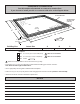
FLOOR FRAME LEVEL AND SQUARE FLOOR FRAME Before attaching floor decking, it is important to level and square the floor frame. A level and square floor frame is required to correctly construct your shed. BEGIN 1 See page 7 for the preferred floor leveling method. 2 Using a level, ensure that the frame is level before applying floor panels. 3 Check for frame squareness by measuring diagonally across corners. If the measurements are the same, the frame is square.
IMPORTANT! Check that the floor frame is level after installing floor panels. Re-level if needed. • The floor should be used as a level work surface for wall construction. HINT: • Organize your wall sections during sub-assembly to avoid over-handling of the walls.
DOOR HEADER PARTS REQUIRED: x2 x18 TCA 3" (7,6 cm) 2 x 4 x 51" (5,1 x 10,2 x 128,9 cm) x1 7/16 x 3-1/4 x 58-3/4" (1,1 x 8,3 x 149,2 cm) OSB BEGIN 1 Stack TCA and OSB as shown. Nail with 3" nails in the pattern shown. 2 ASSEMBLED END VIEW Flip header assembly over and nail as shown on the other side. TCA Flush TER CEN OSB Flush ER T CEN KMA FINISH Your door header is now assembled.
STOP CHOOSE YOUR DOOR LOCATION AT THIS TIME AS YOU WILL ASSEMBLE YOUR DOOR WALL FIRST. STANDARD: DOOR LOCATED ON 8' GABLE WALL 8' GABLE WALL WITH DOOR: IF YOU CHOOSE THE GABLE WALL FOR DOOR LOCATION GO TO Page 13 TO BEGIN BUILDING YOUR WALLS. OPTIONAL: DOOR LOCATED ON 10' EAVE WALL 10' EAVE WALL WITH DOOR: IF YOU CHOOSE THE EAVE WALL FOR DOOR LOCATION GO TO Page 15 TO BEGIN BUILDING YOUR WALLS.
8' WALL WITH DOOR PARTS REQUIRED: x42 3" (7,6 cm) x2 YFA 2 x 4 x 68-1/2" (5,1 x 10,2 x 174 cm) x2 TM 2 x 4 x 72" (5,1 x 10,2 x 182,9 cm) x2 SZ 2 x 4 x 89" (5 x 10,2 x 226,1 cm) Pre-Assembled Header x1 BEGIN 1 Orient parts on edge on floor. Measure and mark. Maintain a 48" (121,9 cm) measurement in door opening (between YFA). Secure with (2) 3" nails at each mark. 89" (226,1 cm) SZ 70 3/4" (179,7 cm) HINT: For easier nailing stand on frame.
8' WALL WITH DOOR PARTS REQUIRED: x54 2" (5,1 cm) x1 3/8 x 3-7/8 x 48" (1 x 9,8 x 121,9 cm) x2 3/8 x 23-7/8 x 76" (1 x 60,6 x 193 cm) Install all panels with the primed side facing up. 2 Place (2) 23-7/8" x 76" panels and 3-7/8" x 48" panel on wall frame as shown. Flush all panels to top plate and flush the 23-7/8" x 76" panels along edge of door frame. Panels will overlap the frame approximately 3-1/2" (8,9 cm) at each side. Secure panels with 2" nails spaced 6" apart.
10' WALL WITH DOOR PARTS REQUIRED: x1 RL x36 2 x 4 x 48" (5,1 x 10,2 x 121,9 cm) 2 x 4 x 24" (5,1 x 10,2 x 61 cm) x7 3" (7,6 cm) x1 SP Pre-Assembled Header x1 TM 2 x 4 x 72" (5,1 x 10,2 x 182,9 cm) x1 TP 2 x 4 x 96" (5,1 x 10,2 x 243,8 cm) BEGIN 1 Orient parts on edge on floor as shown. Measure and mark. HINT: For easier nailing stand on frame. Secure parts with (2) 3" nails at each mark and (4) 3" nails at seams.
10' WALL WITH DOOR PARTS REQUIRED: x114 x1 2" (5,1 cm) 3/8 x 3-7/8 x 48" (1 x 9,8 x 121,9 cm) x1 OO x1 x1 3/8 x 24 x 76" (1 x 61 x 193 cm) 3/8 x 48 x 76" (1 x121,9 x 193 cm) Temporary Brace 69" (75,3 cm) Door Stiffener Install all panels with the primed side facing up. 2 Place 48" x 76" and 24" x 76" and 3-7/8" x 48" panel on wall frame as shown. Flush all panels to top plate and flush the 48" x 76" and 24" x 76" panels along edge of door frame.
10' WALL - NO DOOR PARTS REQUIRED: x1 RL x28 2 x 4 x 48" (5,1 x 10,2 x 121,9 cm) 2 x 4 x 24" (5,1 x 10,2 x 61 cm) x7 3" (7,6 cm) x1 SP TM 2 x 4 x 72" (5,1 x 10,2 x 182,9 cm) x1 TP 2 x 4 x 96" (5,1 x 10,2 x 243,8 cm) IF YOUR DOOR IS ON THE GABLE WALL YOU WILL BUILD TWO IDENTICAL WALLS. IF YOUR DOOR IS ON THE EAVE WALL YOU WILL BUILD ONLY ONE WALL. BEGIN 1 Orient parts on edge on floor as shown. Measure and mark. HINT: For easier nailing stand on frame.
10' WALL - NO DOOR PARTS REQUIRED: x45 2" (5,1 cm) 3/4" GAUGE BLOCK x1 3/8 x 48 x 76" (1 x 121,9 x 193 cm) Install all panels with the primed side facing up. Ensure your wall frame is square by installing one panel and squaring frame. 2 Place (1) 48" x 76" panel on wall frame as shown. Use the GAA gauge block to mark the 3/4" measurement on the wall stud. Secure panel with (2) 2" nails in the corners (Fig. A). 3 Move to the opposite end.
10' WALL - NO DOOR PARTS REQUIRED: x77 2" (5,1 cm) x1 x1 3/8 x 48 x 76" (1 x 121,9 x 193 cm) 4 3/8 x 24 x 76" (1 x 61 x 193 cm) Install (1) 24" x 76" and (1) 48" x76" panels flush to installed panels and flush to top of frame. Secure the panels with 2" nails spaced 6" apart on edges and 12" apart inside panel. Flush Flush 2" (5,1 cm) Nails 6" (15,2 cm) Flush Flush 12" (30,5 cm) Carefully flip your eave wall over. Repeat STEPS 1 - 4 to build a second eave wall if your door is on the gable side.
"A" GABLE WALL PARTS REQUIRED: x12 3" (7,6 cm) x3 TM 2 x 4 x 72" (5,1 x 10,2 x 182,9 cm) x2 SZ 2 x 4 x 89" (5,1 x 10,2 x 226,1 cm) IF YOUR DOOR IS ON THE GABLE WALL YOU WILL BUILD (1) IF YOUR DOOR IS ON THE 10' EAVE WALL YOU WILL BUILD 1 "A" GABLE WALL. "A" and 1 "B" GABLE WALL (P. 22). BEGIN 1 Orient parts on edge on floor as shown. Measure and mark. Secure parts with (2) 3" nails at each mark.
"A" GABLE WALL PARTS REQUIRED: x64 2" (5,1 cm) 3/8 x 48 x 76" (1 x 121,9 x 193 cm) x2 3/4" GAUGE BLOCK Install all panels with the primed side facing up. Install (2) 48" x 76" panels on frame flush at top. Use the gauge block GAA to maintain a 3/4" measurement on the wall stud. Panels will overlap the frame approximately 3-1/2" (8.9 cm) at each side. Secure panels with 2" nails spaced 6" apart along edges and 12" inside panel.
"B" GABLE WALL PARTS REQUIRED: x12 3" (7,6 cm) x3 TM 2 x 4 x 72" (5,1 x 10,2 x 182,9 cm) x2 SZ 2 x 4 x 89" (5,1 x 10,2 x 226,1 cm) BEGIN 1 Orient parts on edge on floor as shown. Measure and mark. Secure parts with (2) 3" nails at each mark.
"B" GABLE WALL PARTS REQUIRED: x83 2" (5,1 cm) x2 3/8 x 23-7/8 x 76" (1 x 60,6 x 193 cm) 3/8 x 48 x 76" (1 x 121,9 x 193 cm) x1 3/4" GAUGE BLOCK Install all panels with the primed side facing up. Place (1) 48" x 76" and (2) 23-7/8" x 76" panels on frame flush at top. Install 48" x 76" panel first. Use the gauge block GAA to maintain 3/4" measurement on the wall stud. Panels will overlap the frame approximately 3-1/2" (8.9 cm) at each side.
STOP STANDING YOUR WALLS The following steps show how to stand and secure your walls. These instructions are by default with the door on the gable wall.
10' WALL INSTALLATION PARTS REQUIRED: x1 x10 3" (7,6 cm) OO 69" (175,3 cm) Door Stiffener x2 3" (7,6 cm) x23 2" (5,1 cm) BEGIN 1 Center 10' wall on the 120" (304,8 cm) floor dimension. 1" (2,5 cm) overlap is to the bottom. Use OO as a temporary brace. Secure with (2) 3" screws. 3" (7,6 cm) Screws D OO O O R 1" (2,5 cm) 2 Secure lower edge of panel to floor frame with 2" nails spaced 6" apart. Angle nails into floor frame (Fig. A). 3 Secure wall bottom plates to floor with 3" nails (Fig. A).
GABLE WALL INSTALLATION PARTS REQUIRED x1 x2 3" (7,6 cm) x18 2" (5,1 cm) x11 1-1/2" (3,8 cm) x8 3" (7,6 cm) Fig. B BEGIN 1 2" (5,1 cm) Place gable wall centered on floor. Secure wall with one 2" screw into 10' wall bottom plate (Fig. A) and top plate (Fig. B). 2" (5,1 cm) Screw Flush Secure wall to bottom plate first. ENSURE PANEL CORNERS ARE FLUSH. 2" (5,1 cm) Screw Fig. A 2 Nail lower edge of panels to floor with 2" nails spaced 6" apart. Angle nails into floor frame (Fig. C).
10' WALL INSTALLATION PARTS REQUIRED: x2 2" (5,1 cm) BEGIN 1 Center 10' wall on the 120" (304,8 cm) floor dimension. OPTIONAL: DOOR LOCATED ON 10' EAVE WALL 2 Secure wall with (1) 2" screw through gable wall panel into 10' wall bottom and top plates (Fig. B, Fig. A). Fig. B 2" (5,1 cm) Screw Secure wall to bottom plate first. ENSURE PANEL CORNERS ARE FLUSH. Flush Fig.
10' WALL INSTALLATION PARTS REQUIRED: x23 3" (7,6 cm) x1 2" (5,1 cm) 3" (7,6 cm) x11 3 x10 1-1/2" (3,8 cm) Nail lower edge of 10' wall panels to floor frame with 2" nails spaced 6" apart. Angle nails into floor frame (Fig. C). Secure wall bottom plates to floor with 3" nails (Fig. C). 3" (7,6 cm) Nails 6" (15,2 cm) Nail 2" nails first. 3" (7,6 cm) Nails 2" (5,1 cm) Nails Fig. C 3" (7,6 cm) Screw 4 Nail gable wall panel to 10' wall stud with 1-1/2" nails spaced 6" apart.
GABLE WALL INSTALLATION PARTS REQUIRED x2 x4 3" (7,6 cm) x10 2" (5,1 cm) 2" (5,1 cm) x4 x22 3" (7,6 cm) 1-1/2" (3,8 cm) REMOVE TEMPORARY BRACING Fig. B 2" (5,1 cm) Screw BEGIN 1 Place 8' wall on floor centered between 10' walls. Secure wall using 2" screws into top and bottom plates (Fig. A, Fig. B). Secure wall to bottom plate first. Flush ENSURE PANEL CORNERS ARE FLUSH. STANDARD: DOOR LOCATED ON 8' GABLE WALL Flush 2" (5,1 cm) Screw Fig.
RAFTERS PARTS REQUIRED: Temporary Support x10 x120 2" (5,1 cm) x1 AL 2 x 4 x 7" (5,1 x 10,2 x 17,8 cm) x12 2 x 4 x 55-9/16" (5,1 x 10,2 x 141,1 cm) You will build 6 rafter assemblies. BEGIN 1 Place (2) rafters on top of temporary support AL and flush to inside of 10' eave wall panels. Place gusset on top of rafters with 1/4" (19 mm) offset (Fig. A). Fasten gusset to rafters with (12) 2" nails in pattern shown. 2 For (2) rafters install (1) gusset and set aside. (Fig. B).
RAFTER INSTALLATION PARTS REQUIRED: x24 Pre-assembled Rafter with 2 Gussets x4 x2 3" (7,6 cm) Pre-assembled Rafter with 1 Gusset BEGIN 1 Secure rafters to top plate at measurements shown with (2) 3" screws in rafter ends (Fig. A). Install single-gusset rafters at each end, with gusset facing inward. 24-3/8" (61,9 cm) Flush to outside of panel 24" (61 cm) 24" (61 cm) 24" (61 cm) 24-3/8" (61,9 cm) Flush to outside of panel Fig.
GABLE UNITS PARTS REQUIRED: x24 1-1/2" (3,8 cm) x4 AL 2 x 4 x 7" (5,1 x 10,2 x 17,8 cm) x2 x2 Install gable panels with the primed side facing up. BEGIN 1 Orient parts AL on the flat side, as shown. Place left gable panel as shown. Secure with 1-1/2" nails as shown. 1-3/4" (4,5 cm) 1-1/2" (3,8 cm) Nails AL (on flat) Flush 1-1/2" (3,8 cm) 2 Place right gable panel flush to left panel. Secure with 1-1/2" nails as shown. 1-1/2" (3,8 cm) Nails Flush Flush Repeat steps to build a 2nd gable unit.
GABLE UNIT INSTALLATION PARTS REQUIRED: x76 1-1/2" (3,8 cm) x4 3" (7,6 cm) x2 Gable Units BEGIN 1 Place gable unit on front wall top plate. Measure 1-1/2" down from top plate and mark at each side as shown. Set gable unit on top plate. Hold secure with (1) 2" nail on each side. BE SURE GABLE IS CENTERED ON WALL BEFORE NAILING. 2 Continue nailing lower edge of panels into top plate with 2" nails spaced 6" apart.
DOORS PARTS REQUIRED: x2 OO x1 1-1/4" (3,2 cm) 69" (175,3 cm) Door Stiffener x4 GAA 3" (7,6 cm) 3/4" GAUGE BLOCK x1 Left Door x1 Right Door BEGIN 1 Orient parts as shown on flat surface. 3/8" offset is to top. Look for red (right) and green (left) on hinge board. Install temporary support OO with 3" screws. Install temporary support GAA at bottom with 1-1/4" screws.
DOORS PARTS REQUIRED: x12 OO x1 3" (7,6 cm) 69" (175,3 cm) Door Stiffener BEGIN 1 Install temporary support OO flush under wall panels. Secure OO with (2) 3" screws (Fig. A). OO Fig. A Flush against wall panels. OO 2 Center doors in door opening as shown (Fig. B). Fasten hinge boards to wall framing and floor with (10) 3" screws as shown. Center in door opening Fig. B 3/8" (1 cm) 3" (7,6 cm) Screws Remove temporary supports and check that the doors open properly.
DOOR TRIM PARTS REQUIRED: x46 x2 EGB 19/32" x 2-1/2 x 18-5/8" (1,5 x 6,3 x 47,3 cm) x2 UWA 19/32" x 3 x 32" (1,5 x 7,6 x 81,3 cm) x1 ZB x5 2" (5,1 cm) 3/4" (1,9 cm) 19/32" x 2-1/2 x 55" (1,5 x 6,3 x 139,7 cm) BEGIN 1 Secure door trim from inside with 3/4" screws, as shown (Fig. A). Attach door trim EGB and UWA with 3/4" screws from inside of doors. 2 Reinforce the door trim with 3/4" screws through door panel into trim (Fig. A). Locate screws as shown (Fig. B). Use (2) screws at seams.
DOOR STIFFENERS PARTS REQUIRED: x2 x14 2" (5,1 cm) OO 69" (175,3 cm) Door Stiffener BEGIN 1 Center OO vertically on the left door in the doorway (Fig. A) overlapping 1" (2,5 cm) along the edge of door (Fig. B). Secure with (7) 2" screws through outside trim into OO. 2 Center OO vertically on the right door in the door opening offset 1" (2,5 cm) from the edge of door (Fig. B). Secure with (7) 2" screws through outside trim into OO. Fig.
DOOR HARDWARE PARTS REQUIRED: x2 1-1/2" (3,8 cm) x1 1/4" (0,6 cm) 1/2" (1,3 cm) Drill Bits BEGIN 1 Measure and mark position on right door as shown. Pre-drill 1/4" hole at mark. Re-drill the hole using a 1/2" drill bit. 2 Position hardware in hole and secure with screws as shown. INSTALL ON RIGHT DOOR. TOP VIEW 1-3/4" (4,4 cm) 35-3/4" (90,8 cm) 1-3/4" (4,4 cm) 1/4" Pre-drill and 1/2" Drill-through. 1-1/2" (3,8 cm) Screws x2 Set Screw FINISH Your door handle is now installed.
DOOR HARDWARE PARTS REQUIRED: x8 x2 5/16" (0,8 cm) Drill Bit 3/4" (1,9 cm) BEGIN 1 Place bolt on OO in open position with bolt end 3/8" (0,8 cm) down from frame. Bolt is open when loop is contacting base (Fig A). 2 Mark and pre-drill holes for screws. Install bolt with screws supplied. Drill 5/16" (0,8 cm) hole deep enough for bolt to slide into. 3 Place bolt on OO in open position with bolt end 1/2" (1,3 cm) up from floor. Bolt is open when loop is connecting base (Fig. B).
ROOF PANELS PARTS REQUIRED: x4 2" (5,1 cm) x1 3/4" GAUGE BLOCK 48 x 96" (121,9 x 243,8 cm) Roof panels may cause serious injury until securely fastened. Note: Install all roof panels with the rough side up (painted grid lines). BEGIN 1 Place the 48" x 96" panel on rafters with a 3/4" measurement on the rafter (Fig A) and the panel flush at the peak (Fig. B). Secure panel with (2) 2" nails in the corners. Flush at peak Fig. B 48 "x 96 " Gauge Block Two Nails Fig.
ROOF PANELS PARTS REQUIRED: x10 2" (5,1 cm) x1 13-7/8 x 23-7/8" (35,2 x 60,6 cm) 3 Install a 13-7/8" x 23-7/8" roof panel flush to the installed panel and flush at peak (Fig. B). Flush at peak Secure panel with (2) 2" nails in the corners. 13 -7/ Two Nails 4 Move the gable until it is at 1/2" (Fig. C) from the 13-7/8" x 23-7/8" roof panel. 8" Fig. B x2 3-7 /8 " Flush Finish securing panel with (2) 2" nails in the corners. Mo ve Ga ble 1/2" (1,2 cm) Fig.
ROOF PANELS PARTS REQUIRED: x8 2" (5,1 cm) 3/4" GAUGE BLOCK 6 x1 x1 13-7/8 x 96" (35,2 x 243,8 cm) 23-7/8 x 48" (60,6 x 121,9 cm) Install 23-7/8" x 48" and 13-7/8" x 96" roof panels with a 3/4" measurement on the rafter (Fig A) and flush to the installed panels. Secure panel with (1) 2" nail in each corner. 2" (5,1 cm) Nails Flush Flush 13 -7/ 8" x9 Flush 6" 3/4" (1,9 cm) Flush 23 -7/ 8" Fig.
ROOF PANELS PARTS REQUIRED: x108 2" (5,1 cm) 7 Secure all roof panels with 2" nails spaced 6" apart on edges and 12" apart inside panel. 6" (15,2 cm) (30 12" ,5 cm ) Repeat steps to install roof panels on the opposite side. FINISH Your roof panels are now installed.
GABLE TRIM PARTS REQUIRED: x24 2" (5,1 cm) x4 NXC 2 x 4 x 62-3/16" (5,1 x 10,2 x 158 cm) x1 HUL 19/32 x 3-1/2 x 62-3/16" (1,5 x 8,9 x 158 cm) x1 HUR 19/32 x 3-1/2 x 62-3/16" (1,5 x8,9 x 158 cm) BEGIN 1 Place parts HUL and HUR primed side down on top of 2x4 parts NXC. Assemble parts flush at corners, as shown. Secure parts with 2" nails spaced evenly.
GABLE TRIM PARTS REQUIRED: Pre-Assembled x24 2" (5,1 cm) Pre-Assembled BEGIN 1 Install assembled gable trim pieces flush to roof panels (Fig. A). Secure gable pieces with 2" screws spaced evenly. Flush with roof panels Fig. A Flush at peak Flush Flush 2" (5,1 cm) Screws Repeat steps for opposite side of shed. FINISH Your gable trim is now installed.
EAVE SOFFIT PARTS REQUIRED: x74 1-1/4" (3,2 cm) x2 HJD 2 x 6 x 25-3/4" (5,1 x 15,2 x 65,4 cm) x2 VX 2 x 6 x 96" (5,1 x 15,2 x 243,8 cm) BEGIN 1 Install HJD flush to VX and flush to roof panels (Fig. A). Secure with 1-1/4" screws evenly spaced and following the pattern shown. **Soffit may need to be trimmed to fit** VX Flush 9-1/2" (24,1 cm) APPROX. HJD 1-1/4" (3,2 cm) Screws HJD Flush Flush to rafter end VX Fig. A FINISH Your eave soffits are now installed.
GABLE FASCIA PARTS REQUIRED: x28 2" (5,1 cm) x1 YOL 19/32" x 2-1/2 x 63-1/16" (1,5 x 6,3 x 160,2 cm) x1 YOR 19/32" x 2-1/2 x 63-1/16" (1,5 x 6,3 x 160,2 cm) BEGIN 1 Install gable trim YOL and YOR flush to roof panels (Fig. A). Secure trim with 2" finishing nails evenly spaced. Flush at peak Flush Flush 2" (5,1 cm) Finishing Nails YOR YOL Repeat steps for opposite side of shed. FINISH Your gable trim is now installed.
EAVE FASCIA x16 PARTS REQUIRED: 2" (5,1 cm) x1 IBA 19/32" x 2-1/2 x 38-3/4" (1,5 x 6,3 x 98,4 cm) x1 BSA 19/32" x 2-1/2 x 91" (1,5 x 6,3 x 231,1 cm) BEGIN 1 Install eave trim IBA flush to BSA and flush to top of roof panels. Fasten trim to 2 x 6 soffit with 2" finishing nails evenly spaced. Flush Flush Flush IBA BSA Repeat steps for opposite side of shed. FINISH Your eave fascia trim is now installed.
CORNER TRIM PARTS REQUIRED: x56 2" (5,1 cm) x8 3/8 x 1-3/4 x 75-3/4" (1 x 4,4 x 192,4 cm) BEGIN 1 Install gable end 75-3/4" corner trim under gable panel,(Fig. A) and flush to eave wall panel (Fig. B). Secure with 2" finishing nails spaced evenly. 2 Install eave side 75-3/4" corner trim flush to eave soffit and flush along seam of installed corner trim (Fig. C). Secure with 2" finishing nails spaced evenly. Fig. B Flush to eave panel Fig.
COLLAR TIES PARTS REQUIRED: x12 2" (5,1 cm) x2 WO 1 x 4 x 72" (2,5 x 10,2 x 182,9 cm) BEGIN 1 Position and level (2) collar ties WO on 2nd rafters from each gable. HINT: For best appearance install collar tie on rafter facing away from a doorway. Secure collar ties with 2" nails as shown. Flush 2" (5,1 cm) Nails Flush Flush Flush FINISH Your collar ties are now installed.
GABLE VENTS PARTS REQUIRED: x8 1" (2,5 cm) x2 ¸1 BEGIN Install (1) vent in each gable. Caulk behind vent flanges. Secure with 1" screws. FINISH Your gable vents are installed.
PAINT & CAULK - NOT INCLUDED - PARTS REQUIRED: • Use acrylic latex caulk that is paintable. Caulk at all horizontal and vertical seams, between the trim and walls, and all around the door trim. • Use a high quality exterior acrylic latex paint. When painting your building, there are a few key areas that can be easily overlooked that must be painted: • Bottom edge of all siding and trim • Inside of doors and all 4 edges Note: Prime all un-primed exterior wood before painting.
SHINGLES - NOT INCLUDED • Follow directions provided by manufacturer and these instructions. Familiarize yourself with a 3-Tab Shingle. Notch Notch SHINGLE NAIL PATTERN 1" (2,5cm) 1/2" (1,3cm) Sealing Str ip 1" (2,5cm) Half A Rain Slot Full Rain Slot NAILS NEVER DRIVE FASTENERS INTO OR ABOVE SEALING STRIPS. BEGIN 1 Install first starter row upside down and color up with a 1" overhang at back and bottom of roof panel. Use (4) nails per shingle.
SHINGLES continued... 3 Install second row of shingles flush at top of first row's rain slots. Ensure 1" overhang or flush to drip edge at front, stagger each row. FRONT OF SHED BACK OF SHED Bend in roof 1" (2,5 cm) Notch Flush with rain slots. 4 Continue installing rows of shingles by staggering at front. Flush with rain slots. 1" (2,5 cm) FRONT OF SHED Notch 5 The shingle over the bend in the roof will be nailed down.
SHINGLES continued... After shingles are installed over bend, nail down overlap with two roofing nails per tab. 6 (2) Nails per tab. 7 Continue installing rows of shingles to the peak. At the peak make sure there is a maximum of 5" or less to the rain slot, as shown below. If shingles overlap at ridge cut to peak using a utility knife. Cut Off. 5" (12,7 cm) MAX. CUT Top of rain slot. 5" (12,7 cm) or less. • If more than 5" to rain slot you must install another row of shingles.
SHINGLES - RIDGE CAP • You will finish off the top of the roof with a ridge cap made from shingles. BEGIN 1 Cut shingles into THREE pieces. 2" (5,1 cm) Hint: Use cut-off pieces first. 2" (5,1 cm) 2" (5,1 cm) 2" (5,1 cm) 2" (5,1 cm) 2" (5,1 cm) Score shingle, then snap-off angled cut. Weather Seal Top of slot. Note: • You will need about 28-30 cut pieces. 2 28 to 30 Pieces Install first ridge cap flush to shingles at front, as shown. (1) Nail per side through weather seal.
SHINGLES - RIDGE CAP continued... 4 Continue installing ridge cap to back of roof. 5 Make sure there is 4" (10,2 cm) between the shingle-color and edge of shingles. 4" (10,2 cm) 6 Trim cap off flush to shingles When you have 4" minimum of shingle color cut one piece to cap your roof. Cut at top of rain slot. Cap 7 Install flush to shingles. Flush to shingles (2) Nails per side. FINISH You have finished your ridge cap.
16569 8' x10' Order Form CATEGORY PART DESCRIPTION PART SIZE PART ITEM # BUILDING QTY.
LIMITED CONDITIONAL WARRANTY* Backyard Storage Solutions, LLC warrants the following: 1. Every product is warranted from defects in workmanship and manufacturing for 1 year. 2. All accessories, hardware and metal components are warranted for 2 years. 3. All Oriented Strand Board (OSB) is warranted for 2 years 4. Siding and Trim is warranted for 15 years. 5. LP Prostruct® Flooring is warranted for 10 years 6. Cedar lumber is warranted for 15 years. 7. Preserved Pine is warranted for 10 years. 8.