
Manual

26
Required Parts
• Fuselage assembly • Firewall template
• Engine mount (2) • #8 washer (12)
• 8-32 locknut (4) • Throttle pushrod
• Throttle pushrod tube • Metal clevis (2)
• Battery cover • #4 washer (4)
• 8-32 blind nut (4)
• Cowl screw fuel tubing (4)
• 4-40 x 1/2-inch socket head screw (4)
• #2 x 1/2-inch sheet metal screw (2)
• Threaded rod, 1-inch (25mm) (2)
• 8-32 x 1
1
/
4
-inch socket head screw (4)
• 8-32 x 1
1
/
2
-inch socket head screw (4)
Required Tools and Adhesives
• Drill • Threadlock
• Clamp • Medium CA
• Phillips screwdriver
• Hex wrench: 3/32-inch, 9/64-inch
• Drill bit: 1/16-inch (1.5mm), 5/32-inch (4mm),
3/16-inch (4.5mm)
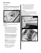
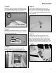
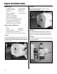
Step 1
Place the firewall template in position on the firewall. Drill
the locations for your particular engine using a 1/16-inch
(1.5mm) drill bit. Drill the location for the throttle pushrod
at this time as well.
Step 2
Remove the template and enlarge the holes using a
3/16-inch (4.5mm) drill bit.
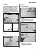
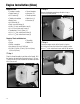
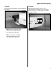
Step 3
Secure the engine mounts to the firewall using four
8-32 blind nuts from the inside of the fuselage, and four
8-32 x 1
1
/
4
-inch socket head screws and four #8 washers.
Engine Installation (Glow)