® TM WE GET PEOPLE FLYING Edge 540 ASSEMBLY MANUAL Specifications Wingspan: .............. 97.5 in (2476.5mm) Length: ................... 85 in (2159mm) Wing Area: ............ 1730.6 sq in (111.65 sq dm) Weight: ................... 22.5–25.5 lb (10.2 kg–11.5 kg) Radio: ..................... 4-channel w/8 servos • Superior controllability and aerobatic flight characteristics Engines: ................... 3.8–4.
Table of Contents Using the Manual . . . . . . . . . . . . . . . . . . . . . . . . . . . . . . . . . . . . . . . . . . . . . . . . . . . . . . . . . . . . . . 2 Table of Contents . . . . . . . . . . . . . . . . . . . . . . . . . . . . . . . . . . . . . . . . . . . . . . . . . . . . . . . . . . . . . . 2 Other Items Needed (not included in the kit) . . . . . . . . . . . . . . . . . . . . . . . . . . . . . . . . . . . . . . . . . . 3 Additional Required Equipment . . . . . . . . . . . . . . . . . . . . . . .
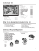
Contents of Kit B I A G H J C E K L F D Items not shown: Landing Gear Fairing Decal Set Anodized Stabilizer Tubes HAN1162 HAN1163 HAN1165 Large Parts A. Fuselage w/Hatch B. Canopy Hatch C. Right Wing Panel w/Aileron D. Left Wing Panel w/Aileron E. Right Stabilizer w/Elevator F. Left Stabilizer w/Elevator G. Rudder H. Canopy I. Painted Cowl J. Carbon Fiber Landing Gear K. Wheel Pants L.
Additional Required Tools and Adhesives Tools • 4-40 tap • 8-32 tap • Adjustable wrench (small) • Canopy scissors • Drill (drill press preferred) • Drill bit: 1/16", 3/32", 7/32", 1/4", #43, 1/2", 5/32", 9/64" • Drum sander • Cut-off wheel • Velcro straps • Flat blade screwdriver w/short handle • Foam: 1/2" • Hex wrench: 3/32" • Hobby knife • Masking tape • Phillips screwdriver (small) • Pliers • Scissors • Square • Syringe • Tap handle • Toothpicks Adhesives • 6-minute epoxy • 30-minute epoxy • Thick CA (
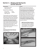
Servo Selection The servos used for the control surfaces of the Edge 540 must have a minimum of 80 ounce inch of servo torque. In the prototype edges, we used JR8411 servos. On the rudder we used ONE JR8611 servo. Two servos are recommended if using other servos on the rudder. Before Starting Assembly Before beginning the assembly of the Edge 540, remove each part from its bag for inspection. Closely inspect the fuselage, wing panels, rudder, and stabilizer for damage.
Section 1 – Aileron Servo Installation Required Parts • Wing panel (right and left) Required Tools and Adhesives • Phillips screwdriver (small) • Drill bit: 1/16" • Drill • 12" Servo Extension (JRPA098) • 24" Servo Extension (JRPA102) Step 1 Install the servo hardware (grommets and eyelets) included with the servo. Step 2 Plug a 12" and a 24" servo extension onto two of the servos.
Section 1 – Aileron Servo Installation Step 4 Insert the servo with the 24" extension towards the tip of the wing. Use the string to pull the servo lead through the wing. Position the servo so the output shaft is towards the trailing edge of the wing. Use a 1/16” drill bit to drill the locations for the servo screws. Mount the servos using the hardware provided with the servos. Photo for Step 4 Photo for Step 4 Step 5 Repeat Steps 3 and 4 for the servo near the root of the wing panel.
Section 2 – Aileron Control Horn Installation Required Parts • Wing panel (left and right) • Aileron (left and right) Required Tools and Adhesives • Felt-tipped pen • Drill bit: 5/32" • 8-32 tap • Tap handle • Square • Ruler • 30-minute epoxy • Rubbing alcohol • Drill (drill press preferred) • 8-32 x 2" Hangar 9® control horn screw (4) (Included in HAN1220 (JR®) or HAN1221 (FUT)) • Hangar 9 control horn hex nut (4) (Included in HAN1220 (JR) or HAN1221 (FUT)) Step 1 Tape the aileron to the wing.
Section 2 – Aileron Control Horn Installation Note: A hardwood block (hard point) is located below the sheeting; you will be drilling through this. Make sure to drill the hole perpendicular to the top of the aileron. It is highly recommended to use a drill press to achieve this. Photo for Step 6 Photo for Step 5 Step 7 Mix a small amount of 30-minute epoxy and lightly coat the inside of the tapped hole and the 8-32 x 2" Hangar 9® control horn screw.
Section 3 – Hinging and Sealing the Control Surfaces Required Parts • Wing panel (right and left) • Aileron (left and right) Required Tools and Adhesives • 30-minute epoxy • Syringe • Sandpaper (coarse) • Toothpicks • Robart hinge points Properly hinging the control surfaces on giant-scale models is vitally important! Poorly installed hinges affect the model’s precision and control response and can also be dangerous.
Section 3 – Hinging and Sealing the Control Surfaces Step 3 Allow the epoxy to fully cure for at least 6 hours. When cured, work each hinge throughout its full motion several times using your hands. This will break free any epoxy that may have found its way into the hinge joint. Move the hinge throughout its full travel until no resistance is felt. This may take as many as 40 or 50 times. Step 5 Carefully attach the aileron to the wing, making sure the hinges are inserted in their respective hinge pockets.
Section 3 – Hinging and Sealing the Control Surfaces Step 7 When fully cured, move each control surface throughout its travel range several times to break away any epoxy in the hinge. Be sure to deflect the surface fully.
Section 4 – Sealing the Hinge Gaps Step 2 Using a ruler, measure 1/2" from the folded crease and mark two places with a felt-tipped pen. Step 4 Mark and cut the folded covering to an overall length of 42". This piece will be inserted and ironed down into the hinge bevel on the bottom of the aileron. Step 3 Using a sharp #11 blade and a straight edge, carefully cut through both layers of UltraCote® covering at the 1/2" point marked in Step 2. Step 5 Remove the backing from the UltraCote.
Section 5 – Aileron Linkage Installation Required Parts • Aluminum servo arms (4) • Control horn ball ends (4) • 41/2" 4-40 linkage (4) Required Tools and Adhesives • Phillips screwdriver (small) • Threadlock MatchBox Option: To simplify the installation of the aileron servo linkages, you may want to use the JR™ MatchBox™ servo matching/power system (JRPA900). Four MatchBoxes would be used in this application—one for each wing panel, one for the rudder and one for the elevator servo configuration.
Section 5 – Aileron Linkage Installation Step 4 Attach the linkage to the servo horn on the aileron. Adjust the link so the aileron is centered at the same time as the servo. Photo for Step 4 Step 5 Repeat Steps 1 through 4 for the second servo. Step 6 Repeat Steps 1 through 5 for the remaining servos in the opposite wing panel.
Section 6 – Wing Installation Required Parts • Wing panels • Fuselage • Wing tube • 1/4-20 x 2" nylon bolts (2) Step 2 Carefully slide the remaining wing panel onto the wing tube that projects from the fuselage. The fit may be tight; use caution when inserting the wing panels onto the wing tube and fuselage. Required Tools and Adhesives • Flat screwdriver w/short handle • Thick CA • Sandpaper (medium) Step 3 Secure the wing panels using the 1/4-20 x 2" nylon wing bolts.
Section 7 – Elevator Assembly Required Parts • Stabilizer (right and left) • Fuselage • Stabilizer tube (small) • Stabilizer tube (large) Step 2 Tie the string around the servo lead. Pull the servo lead through the openings in the stabilizer. Install the servo using the hardware provided with the servo.
Section 7 – Elevator Assembly Note: The technique for installing the control horns in the elevators is similar to the aileron control horn installation. Step 4 To properly locate the position of the control horn on the bottom of the elevator, measure inward 7/8" from the root and rearward 1/4" from the top of the bevel. Step 5 Using a 5/32" drill bit and drill press, carefully drill through the elevator at the above marked position. It’s important to drill 90° to the top of the elevator.
Section 7 – Elevator Assembly Step 10 Glue the elevator hinges in place using the same techniques used to hinge the ailerons. The shortened hinges will be installed into the stabilizer towards the root. After hinging the elevator, use the same technique to seal the elevator’s hinge gaps. Use Clear UltraCote® for the bottom of the elevator. Step 11 Assemble and install the elevator linkage using a 2 1/2" titanium linkage. Step 12 Repeat Steps 1 through 11 for the remaining stabilizer and elevator.
Section 7 – Elevator Assembly Step 14 Drill through the hole in the stabilizer and tap for a 4-40 bolt. Install the bolt to secure the tube. Step 15 Slide the stabilizer onto the fuselage. Step 16 Slide the remaining stabilizer onto the tubes and against the fuselage. Drill and tap the location for the 4-40 retaining bolt. Install the bolt to complete the procedure.
Section 8 – Rudder Assembly Required Parts • Rudder • Fuselage Required Tools and Adhesives • Phillips screwdriver • Servo w/hardware • Control horn • Robart hinge points Step 4 Thread a hex nut (included with swivel clevis) onto the threaded rod and securely tighten against the rudder. Screw a molded swivel link onto the threaded rod so the top of the link is 7/8" from the surface of the rudder. Step 1 Mark the position for the rudder control horn with a pen.
Section 9 – Landing Gear Installation Required Parts • Fuselage • Landing gear fairing • 10-32 x 1" socket head bolt (4) • 10-32 nylon lock nut (4) • #10 lock washer (4) • 1/4-20 x 2” nylon bolt Step 2 Install the landing gear using four 10-32 x 1" socket head bolts, four #10 lock washers and four 10-32 nylon lock nuts. (The lock nuts are placed inside the fuselage.) Required Tools and Adhesives • Hobby knife • 5/32" hex wrench • Adjustable wrench (small) Step 1 Install the axles in the landing gear.
Section 10 – Wheel Pant Installation Required Parts • Wheel (2) • 3/16" wheel collar (4) • #4 washer (2) • #4 lock washer (2) • Fuselage w/landing gear • Wheel pant (left and right) • 4-40 x 1/2" socket head screw (2) Required Tools and Adhesives • Drill • Drill bit: 1/2" and 9/64" • Felt-tipped pen • Square • Ruler Step 3 Use a rotary tool or drill to make a 1/2" hole at the location made in the last step. Note: When using drill bits, it is best to start small and work up to the larger size bit.
Section 10 – Wheel Pant Installation Step 5 Remove the pant and use a 9/64" drill bit to drill the location marked in the previous step. Step 6 Install a 4-40 blind nut into the hole from the inside of the pant. The nut will be drawn into the plywood later in this section. Step 7 Secure the pant in place using a 4-40 x 1/2" socket head screw, #4 lock washer, and #4 washer. Use threadlock on the screw to prevent it from coming loose in flight.
Section 11 – Tail Wheel Installation Required Parts • Fuselage • Tail wheel assembly Required Tools and Adhesives • Drill • Drill bit: 3/32" • #6 x 3/4" screw (2) (not included) • Felt-tipped pen Step 1 Assemble the tail wheel per the instructions included with the tail wheel assembly. The nylon control horns included with the tail wheel assembly are not used. Step 4 Use two #6 x 3/4" sheet metal screws to secure the tail wheel bracket in place.
Section 12 – Receiver, Battery and Fuel Tank Installation Required Parts • Fuselage Required Tools and Adhesives • 1/8" light plywood • Velcro straps • 6-minute epoxy Step 1 Use foam and rubber bands (or Velcro® straps) to secure the receiver to the battery tray. Step 4 Assemble the tank per the instructions included with the tank. Be sure to use the gas-compatible stopper and fuel tubing. Step 5 Place foam on the floor of the tank compartment.
Section 13 – Mounting the Engine and Cowl Required Parts • Fuselage assembly • Engine • 1/4" lock washer (4) • 4-40 Ball Links • Fuel Filler (HAN115) • 1/8" plywood • Kill Switch (ZEN20000) • 4-40 x 12" threaded rod (2) • Engine mounting adapter plate (G62 only) • 1/4-20 x 11/2" socket head cap screw (4) (G62) • Cup engine Mount (B&B6202) (G62) • 1/4-20 x 1/2" socket head cap screw (4) (GT80) • 2' Gas-Compatible Fuel Tubing (DUB800) • 18" Servo Extension (JRPA099) Required Tools and Adhesives • Rotary tool
Section 13 – Mounting the Engine and Cowl Step 3 Make up the throttle linkage using a 4-40 rod and two ball links. Carefully tap the throttle arm of the carburetor with a 4-40 tap and connect the ball link to the throttle arm. Use the remaining ball end to attach the linkage to the servo arm. Step 4 Attach a 4-40 rod with a ball link to the choke lever. Route the linkage to the bottom of the fuselage where it can be easily accessed during the starting of the engine.
Section 13 – Mounting the Engine and Cowl Step 3 Mount the throttle servo on the bottom of the engine box 3/4" back from the front edge of the box. Use the hardware supplied with the servo to attach the servo to the engine box. Step 2 Use a rotary tool with a cut-off wheel and drum sander to cut out a large air outlet at the aft edge of the cowling. Also make any necessary cutouts for items such as mufflers, carburetors, linkages, etc.
Section 14 – Hatch Assembly Required Parts • Hatch • 4-40 x 1/2" screw (4) • Decals • Canopy • #4 washer (4) • 1/3-scale pilot Required Tools and Adhesives • Hex wrench: 3/32" • Formula 560-canopy glue • Shoo Goo • Masking tape Step 1 The Edge hatch comes pre-installed on the fuselage and is held on with two 4-40 socket head cap screws. Remove these and lift the hatch from the fuselage. Step 2 Cut out the instrument panel decal from the decal sheet. Attach it to the hatch as shown.
Step 5 Lightly sand the inside edge of the canopy and slightly inside the line drawn on the hatch using medium sandpaper. Step 6 Apply a bead of RCZ56 Canopy Glue (ZINJ5007) around the inside edge of the canopy. Position the canopy onto the hatch. Use tape to hold the canopy secure until the glue fully cures. Step 7 Apply the decals using the photos on the box as a guide. Section 15 – Balancing the Model Correctly balancing an aerobatic model is critical to its performance and flight characteristics.
Section 16 – Radio Setup A 7-channel or greater computer radio is highly recommended.
Preflight at the Field Range Test Your Radio Step 1 Before each flying session, be sure to range check your radio. This is accomplished by turning on your transmitter with the antenna collapsed. Turn on the receiver in your airplane. With your airplane on the ground and the engine running, you should be able to walk 30 paces (approximately 100 feet) away from your airplane and still have complete control of all functions.
The Prototype Model Setup All of the recommended settings in this manual are a result of the flight testing on the prototype Edges. There are no secrets. If you follow the instructions and these tips, your Edge will be set up just like mine. Although a computer radio is not mandatory, it is preferable in this model. I use Exponential on all controls to soften the feel around neutral. This makes it easier to fly smooth in precision maneuvers and also makes it less likely to over-control in 3D mode.
Spoileron Mixing This can be achieved by using either a preprogrammed elevator-to-flap mix or a P-mix. Assign elevator as the master channel and flap as the slave. Set the mix values so that when full up, 3D elevator is given, both ailerons also go up 7/16" (16°). This mix helps stabilize the model in some 3D maneuvers such as the Elevator and Harrier. Throttle Curve This is normally a preprogrammed function.
Unloading Snaps That’s the whole trick. To start a snap roll, the same method as with a smaller model is used. Pull full up, full rudder and aileron in the same direction. But as soon as the sticks reach the corners, neutralize the elevator, while keeping the rudder and ailerons at full deflection. When you do this correctly, the Edge will not get “deep” into snaps. This allows it to keep more airspeed as it exits the snap, so it stops snapping where you what it to and flies out with more air speed.
The Maneuvers Let’s cover the seven 3D maneuvers where the Edge 540 really excels. The Blender What it is: The Blender or Panic maneuver is a vertical diving roll that virtually stops its descent as it instantaneously enters into a flat spin. Setup: Follow the 3D setup as described in the manual. Be sure to use Expo. Setting the CG toward the aft location will help, but I have had great results even at the forward CG location.
The Elevator What it is: The plane drops vertically while in a nose high attitude. Depending on the head wind conditions, the model will drop anywhere from about a 45-degree angle in calm conditions to vertical or even a little backwards in more windy conditions. Throttle is used to determine rate of descent and the nose high attitude of the model. 38 Setup: Same as the Blender, only for this one, flip the switch to turn on the spoilerons. This will help to keep the Edge 540 from teetering back and forth.
The Torque Roll What it is: The Edge 540 “hovers” vertically in place, rotating left around its roll axis. Setup: Full 3D throws in elevator and rudder are a must. An aft CG helps a little. Also gyros provide the best aid to stabilize the aircraft. They won’t do the maneuver for you but they’ll help. I found them a fantastic tool in learning to torque roll, kind of like training wheels. A few years ago gyros made a big difference for me; now I don’t use them anymore.
The Parachute What it is: The Parachute is a vertical dive that instantly decelerates in its descent as it instantaneously corners into an Elevator. 40 Setup: Same as the Elevator, and the raised ailerons help in this maneuver too. How to do it: Start from about 400-500 feet straight and level, chop throttle, and push the nose straight down. As soon as the model is diving straight down at low throttle, add full up-elevator.
The Wall What it is: The Wall is a Parachute turned on end. The model starts in normal level flight and suddenly corners nose up 90 degrees, as if it hit a wall. Worst way to mess up: Don’t get the throttle in quickly enough and the model falls backward. Great combo: This has become one of my favorites to do with the Edge 540. Takeoff normally, but as soon as the Edge is airborne, chop the throttle and do the Wall, then transition into a Torque Roll over the runway.
2004 Official AMA National Model Aircraft Safety Code Effective January 1, 2003 Model Flying MUST be in accordance with this Code in order for AMA Liability Protection to apply. GENERAL 1) I will not fly my model aircraft in sanctioned events, air shows or model flying demonstrations until it has been proven to be airworthy by having been previously, successfully flight tested. 2) I will not fly my model higher than approximately 400 feet within 3 miles of an airport without notifying the airport operator.
2004 Official AMA National Model Aircraft Safety Code Continued 4) I will operate my model using only radio control frequencies currently allowed by the Federal Communications Commission. (Only properly licensed Amateurs are authorized to operate equipment on Amateur Band frequencies.) 5) Flying sites separated by three miles or more are considered safe from site-to site interference, even when both sites use the same frequencies.
® TM WE GET PEOPLE FLYING © 2004, Horizon Hobby, Inc. 4105 Fieldstone Road Champaign, Illinois 61822 (877) 504-0233 www.horizonhobby.