
User Manual


Table Of Contents
- Table of Contents
- Using the Manual
- Contents of Kit
- Other Items Needed (not included in the kit)
- Additional Required Equipment
- Additional Required Tools and Adhesives
- Optional Hangar 9 1/3 Scale Hardware Package
- Servo Selection
- Before Starting Assembly
- Warning
- Warranty Information
- Section 1 - Aileron Servo Installation
- Section 2 - Aileron Control Horn Installation
- Section 3 - Hinging and Sealing the Control Surfaces
- Section 4 - Sealing the Hinge Gaps
- Section 5 - Aileron Linkage Installation
- Section 6 - Wing Tube Installation
- Section 7 - Rudder and Elevator Servo Installation
- Section 8 - Elevator Linkage Installation
- Section 9 - Rudder Linkage Installation
- Section 10 - Landing Gear Installation
- Section 11 - Wheel Pant Installation
- Section 12 - Tail Wheel Installation
- Section 13 - Receiver, Battery and Fuel Tank Installation
- Section 14 - Mounting the Engine and Cowl
- Section 15 - Hatch Assembly
- Section 16 - Balancing the Model
- Section 17 - Radio Setup
- Section 18 - Control Throws
- Preflight at the Field
- Setup and Flying
- Extra 330S - 3D at its Best
- 2003 Official AMA National Model Aircraft Safety Code
Section 8 – Elevator Linkage Installation
19
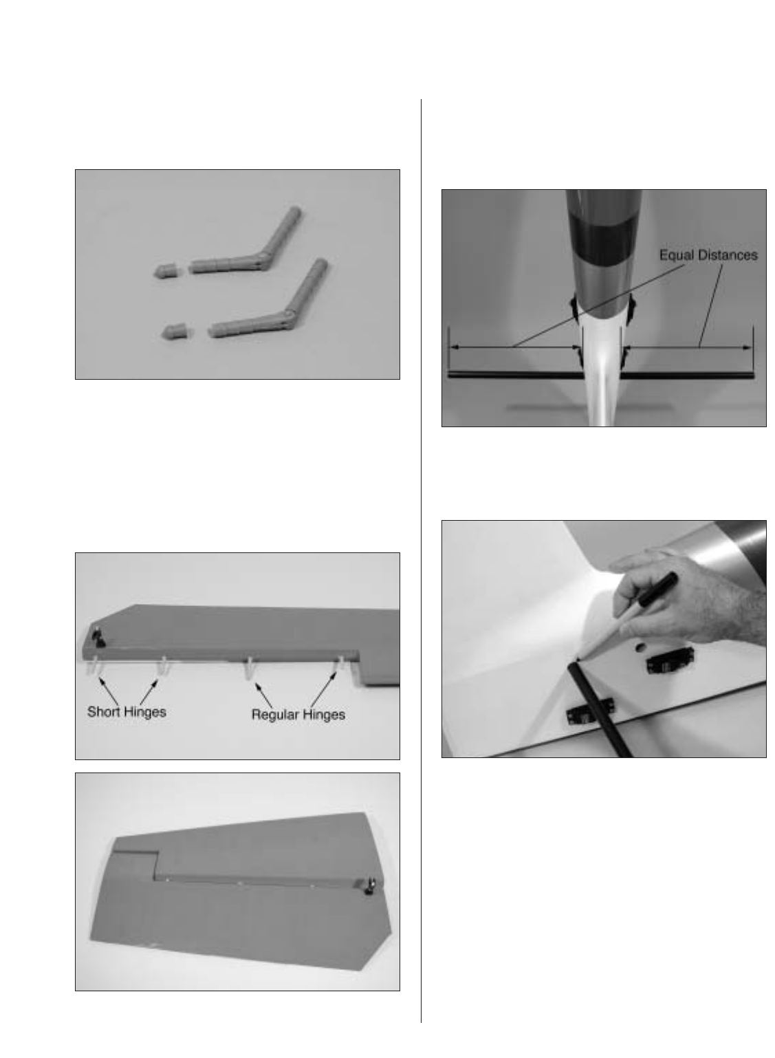
Step 6
Cut off the first section of two of the hinges. This is
done to clear the tube installed in the elevator.
Step 7
Glue the elevator hinges in place using the same
techniques used to hinge the ailerons. The shortened
hinges will be installed into the stabilizer towards the
root. After hinging the elevator, use the same
technique to seal the elevator’s hinge gaps. Use Clear
UltraCote® for the bottom of the elevator.
Step 8
Insert the longer tube into the aft hole in the fuselage.
Measure the distance of the exposed tube and adjust
until both side are equal.
Step 9
Mark the tube on both side of the fuselage using a
felt-tipped pen.