
User Manual


Table Of Contents
- Table of Contents
- Using the Manual
- Contents of Kit
- Other Items Needed (not included in the kit)
- Additional Required Equipment
- Additional Required Tools and Adhesives
- Optional Hangar 9 1/3 Scale Hardware Package
- Servo Selection
- Before Starting Assembly
- Warning
- Warranty Information
- Section 1 - Aileron Servo Installation
- Section 2 - Aileron Control Horn Installation
- Section 3 - Hinging and Sealing the Control Surfaces
- Section 4 - Sealing the Hinge Gaps
- Section 5 - Aileron Linkage Installation
- Section 6 - Wing Tube Installation
- Section 7 - Rudder and Elevator Servo Installation
- Section 8 - Elevator Linkage Installation
- Section 9 - Rudder Linkage Installation
- Section 10 - Landing Gear Installation
- Section 11 - Wheel Pant Installation
- Section 12 - Tail Wheel Installation
- Section 13 - Receiver, Battery and Fuel Tank Installation
- Section 14 - Mounting the Engine and Cowl
- Section 15 - Hatch Assembly
- Section 16 - Balancing the Model
- Section 17 - Radio Setup
- Section 18 - Control Throws
- Preflight at the Field
- Setup and Flying
- Extra 330S - 3D at its Best
- 2003 Official AMA National Model Aircraft Safety Code
20
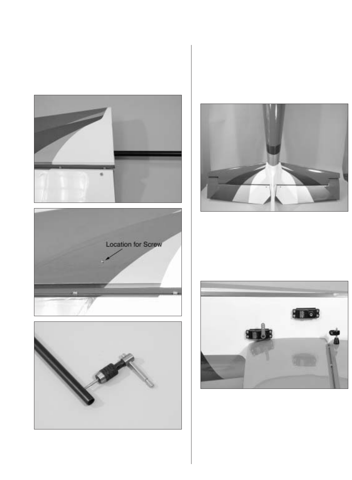
Section 8 – Elevator Linkage Installation
Step 10
Remove the tube and install it into one stabilizer half-
way up to the first line on the tube. Drill through the
hole into the stabilizer and tap for a 4-40 bolt. Install
the bolt to secure the tube in the stabilizer.
Step 11
Install the shorter tube into the stabilizer half with
the secured tube. Slide the assembly into the
fuselage. Slide the remaining stab half onto the tubes
and drill and tap the location for the 4-40 retaining
bolt. Install the bolt to complete the procedure.
Step 12
Remove the stock servo arms from the elevator
servos and replace them with heavy-duty 1" arms.
The arms need to face down as shown. Be sure to
use a drop of threadlock on the servo arm screw if
using metal-geared servos.