
User Manual


Table Of Contents
- Table of Contents
- Using the Manual
- Contents of Kit
- Other Items Needed (not included in the kit)
- Additional Required Equipment
- Additional Required Tools and Adhesives
- Optional Hangar 9 1/3 Scale Hardware Package
- Servo Selection
- Before Starting Assembly
- Warning
- Warranty Information
- Section 1 - Aileron Servo Installation
- Section 2 - Aileron Control Horn Installation
- Section 3 - Hinging and Sealing the Control Surfaces
- Section 4 - Sealing the Hinge Gaps
- Section 5 - Aileron Linkage Installation
- Section 6 - Wing Tube Installation
- Section 7 - Rudder and Elevator Servo Installation
- Section 8 - Elevator Linkage Installation
- Section 9 - Rudder Linkage Installation
- Section 10 - Landing Gear Installation
- Section 11 - Wheel Pant Installation
- Section 12 - Tail Wheel Installation
- Section 13 - Receiver, Battery and Fuel Tank Installation
- Section 14 - Mounting the Engine and Cowl
- Section 15 - Hatch Assembly
- Section 16 - Balancing the Model
- Section 17 - Radio Setup
- Section 18 - Control Throws
- Preflight at the Field
- Setup and Flying
- Extra 330S - 3D at its Best
- 2003 Official AMA National Model Aircraft Safety Code
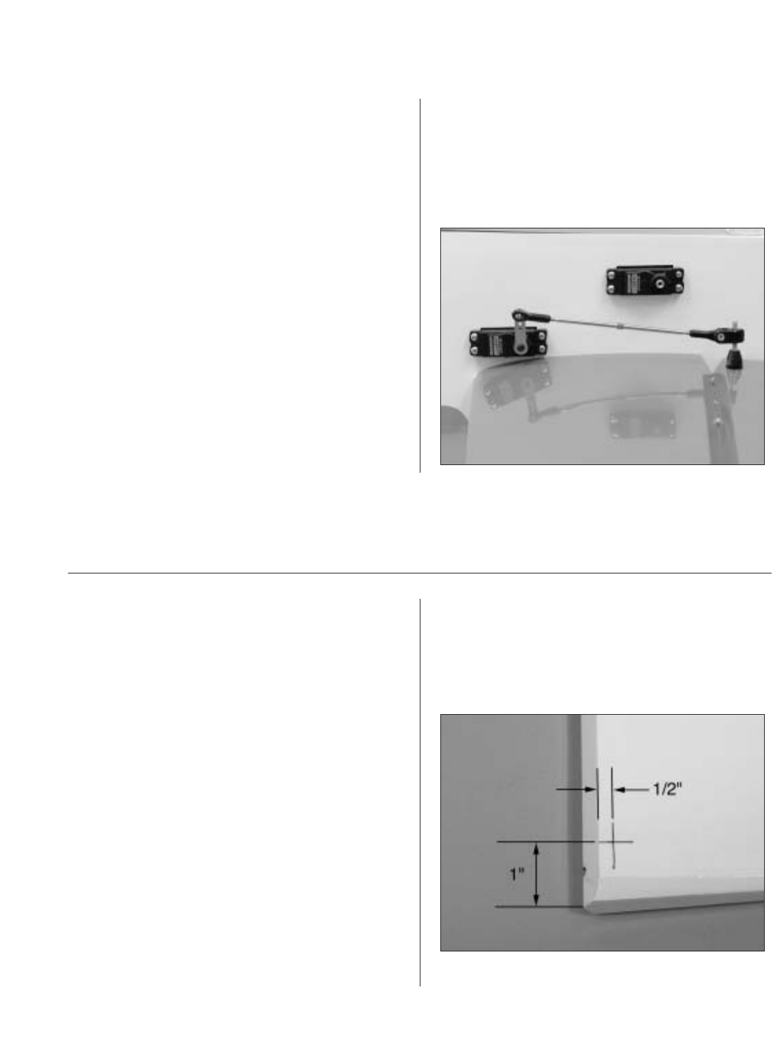
Section 8 – Elevator Linkage Installation
21
Step 13
Screw a 4-40 ball link 5 to 6 turns onto a 4
1
/
2
" long
4-40 linkage. Screw the opposite end of the linkage
into the swivel control horn on the elevator. Adjust
the linkage length until the hole in the ball link lines
up with the outer hole in the servo arm when the
elevator is neutral and the servo arm is centered.
Step 14
Using the 4-40 screws and nuts included in the
Hangar 9
®
package, attach the ball link to the outer
hole in the arm. The correct sequence is 4-40 screw,
ball link, standoff, servo arm and 4-40 nut. Be sure
to use threadlock.
Section 9 – Rudder Linkage Installation
Required Parts
• Rudder • Fuselage assembly
Required Tools and Adhesives
• 8-32 tap • Drill Bit: 5/32"
• Drill • Tap handle
• Thick CA • Rotary tool
• Cut-off wheel • Ruler
• 4-40 linkage
Note: The elevators have been removed for
clarity.
Step 1
Mark the position for the rudder control horn with
a pen. The correct location is 1" up from the bottom
of the rudder and 1/4" rearward from the edge of
the rudder bevel.