
User Manual


Table Of Contents
- Table of Contents
- Using the Manual
- Contents of Kit
- Other Items Needed (not included in the kit)
- Additional Required Equipment
- Additional Required Tools and Adhesives
- Optional Hangar 9 1/3 Scale Hardware Package
- Servo Selection
- Before Starting Assembly
- Warning
- Warranty Information
- Section 1 - Aileron Servo Installation
- Section 2 - Aileron Control Horn Installation
- Section 3 - Hinging and Sealing the Control Surfaces
- Section 4 - Sealing the Hinge Gaps
- Section 5 - Aileron Linkage Installation
- Section 6 - Wing Tube Installation
- Section 7 - Rudder and Elevator Servo Installation
- Section 8 - Elevator Linkage Installation
- Section 9 - Rudder Linkage Installation
- Section 10 - Landing Gear Installation
- Section 11 - Wheel Pant Installation
- Section 12 - Tail Wheel Installation
- Section 13 - Receiver, Battery and Fuel Tank Installation
- Section 14 - Mounting the Engine and Cowl
- Section 15 - Hatch Assembly
- Section 16 - Balancing the Model
- Section 17 - Radio Setup
- Section 18 - Control Throws
- Preflight at the Field
- Setup and Flying
- Extra 330S - 3D at its Best
- 2003 Official AMA National Model Aircraft Safety Code
22
Section 9 – Rudder Linkage Installation
Step 2
Using a 5/32" drill bit and drill press, carefully drill
a 5/32" hole through the rudder perpendicular (90°)
to the rudder centerline at the marked position. Be
especially careful when penetrating through the
backside of the rudder.
Step 3
Using an 8-32 tap, thread the hole that you just
drilled in the rudder.
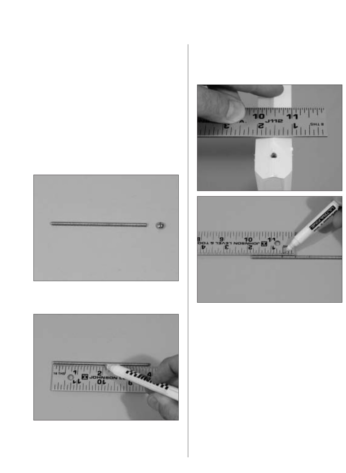
Step 4
Use a rotary tool and cut-off wheel to remove the
head of the 4" bolt.
Step 5
Measure and mark the center of the bolt.
Step 6
Measure the width of the rudder. Divide the
measurement by 2 and make marks on either side
of the center mark the distance calculated.
Step 7
Apply a few drops of thick CA on the bolt at the
center. This will secure the bolt and prevent it
from loosening during flight. Install the bolt using
the lines drawn in the previous step to center the
bolt in the rudder.
Step 8
Thread an A-nut (included with swivel clevis) onto
each side of the threaded rod and securely tighten
against the rudder.