
User Manual


Table Of Contents
- Table of Contents
- Using the Manual
- Contents of Kit
- Other Items Needed (not included in the kit)
- Additional Required Equipment
- Additional Required Tools and Adhesives
- Optional Hangar 9 1/3 Scale Hardware Package
- Servo Selection
- Before Starting Assembly
- Warning
- Warranty Information
- Section 1 - Aileron Servo Installation
- Section 2 - Aileron Control Horn Installation
- Section 3 - Hinging and Sealing the Control Surfaces
- Section 4 - Sealing the Hinge Gaps
- Section 5 - Aileron Linkage Installation
- Section 6 - Wing Tube Installation
- Section 7 - Rudder and Elevator Servo Installation
- Section 8 - Elevator Linkage Installation
- Section 9 - Rudder Linkage Installation
- Section 10 - Landing Gear Installation
- Section 11 - Wheel Pant Installation
- Section 12 - Tail Wheel Installation
- Section 13 - Receiver, Battery and Fuel Tank Installation
- Section 14 - Mounting the Engine and Cowl
- Section 15 - Hatch Assembly
- Section 16 - Balancing the Model
- Section 17 - Radio Setup
- Section 18 - Control Throws
- Preflight at the Field
- Setup and Flying
- Extra 330S - 3D at its Best
- 2003 Official AMA National Model Aircraft Safety Code
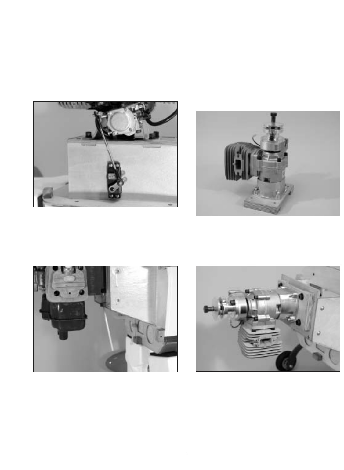
Section 14 – Mounting the Engine and Cowl
31
Step 3
Make up the throttle linkage using a 4-40 rod and
two ball links. Carefully tap the throttle arm of the
carburetor with a 4-40 tap and connect the ball link
to the throttle arm. Use the remaining ball end to
attach the linkage to the servo arm.
Step 4
Attach a 4-40 rod with a ball link to the choke lever.
Route the linkage to the bottom of the fuselage
where it can be easily accessed during the starting
of the engine.
G62 Installation
Step 1
Remove the metal engine mount (if attached) from
the G62. Attach the B+B Cup engine mount. Attach
the cup mount to the adapter plate using the
hardware supplied with the cup mount.
Step 2
Install the adapter plate and engine to the firewall
using 1/4-20 x 1
1
/
2
" socket head screws (not
included), split washers and blind nuts.