
User Manual


Table Of Contents
- Table of Contents
- Using the Manual
- Contents of Kit
- Other Items Needed (not included in the kit)
- Additional Required Equipment
- Additional Required Tools and Adhesives
- Optional Hangar 9 1/3 Scale Hardware Package
- Servo Selection
- Before Starting Assembly
- Warning
- Warranty Information
- Section 1 - Aileron Servo Installation
- Section 2 - Aileron Control Horn Installation
- Section 3 - Hinging and Sealing the Control Surfaces
- Section 4 - Sealing the Hinge Gaps
- Section 5 - Aileron Linkage Installation
- Section 6 - Wing Tube Installation
- Section 7 - Rudder and Elevator Servo Installation
- Section 8 - Elevator Linkage Installation
- Section 9 - Rudder Linkage Installation
- Section 10 - Landing Gear Installation
- Section 11 - Wheel Pant Installation
- Section 12 - Tail Wheel Installation
- Section 13 - Receiver, Battery and Fuel Tank Installation
- Section 14 - Mounting the Engine and Cowl
- Section 15 - Hatch Assembly
- Section 16 - Balancing the Model
- Section 17 - Radio Setup
- Section 18 - Control Throws
- Preflight at the Field
- Setup and Flying
- Extra 330S - 3D at its Best
- 2003 Official AMA National Model Aircraft Safety Code
32
Section 14 – Mounting the Engine and Cowl
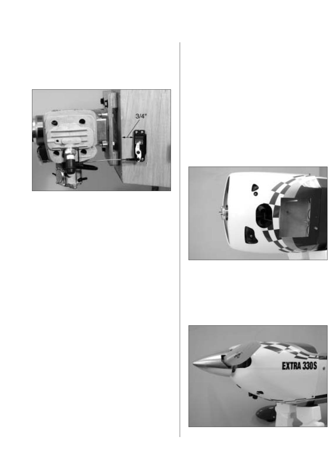
Step 3
Mount the throttle servo on the bottom of the engine
box 3/4" back from the front edge of the box. Use the
hardware supplied with the servo to attach the servo
to the engine box.
Step 4
Use a 4-40 threaded rod and two clevises to make a
throttle pushrod of the appropriate length. Make any
necessary bends in the linkage to prevent binding
during operation.
Step 5
Attach a 4-40 rod with a ball link to the choke lever.
Route the linkage to the bottom of the fuselage
where it can be easily accessed during the starting
of the engine.
Completing the Engine Installation
Step 1
Run the fuel lines from the pick up in the tank to
the carburetor and run the vent line out the bottom of
the firewall. We recommend using a fuel filter and a
kill switch mounted on the fuselage for convenient
fueling and safety.
Step 2
Use a rotary tool with a cut-off wheel and drum
sander to cut out a large air outlet at the aft edge of
the cowling. Also make any necessary cutouts for
items such as mufflers, carburetors, linkages, etc.
Step 3
Mount the cowl using five 4-40 x 3/4" socket head
screws and #4 washers. Use a small piece of fuel
tubing between the cowl and washer to prevent the
screws from vibrating loose during flight. Mount the
propeller and spinner to complete the procedure.