
User Manual


Table Of Contents
- Table of Contents
- Using the Manual
- Contents of Kit
- Other Items Needed (not included in the kit)
- Additional Required Equipment
- Additional Required Tools and Adhesives
- Optional Hangar 9 1/3 Scale Hardware Package
- Servo Selection
- Before Starting Assembly
- Warning
- Warranty Information
- Section 1 - Aileron Servo Installation
- Section 2 - Aileron Control Horn Installation
- Section 3 - Hinging and Sealing the Control Surfaces
- Section 4 - Sealing the Hinge Gaps
- Section 5 - Aileron Linkage Installation
- Section 6 - Wing Tube Installation
- Section 7 - Rudder and Elevator Servo Installation
- Section 8 - Elevator Linkage Installation
- Section 9 - Rudder Linkage Installation
- Section 10 - Landing Gear Installation
- Section 11 - Wheel Pant Installation
- Section 12 - Tail Wheel Installation
- Section 13 - Receiver, Battery and Fuel Tank Installation
- Section 14 - Mounting the Engine and Cowl
- Section 15 - Hatch Assembly
- Section 16 - Balancing the Model
- Section 17 - Radio Setup
- Section 18 - Control Throws
- Preflight at the Field
- Setup and Flying
- Extra 330S - 3D at its Best
- 2003 Official AMA National Model Aircraft Safety Code
8
Section 2 – Aileron Control Horn Installation
Required Parts
• Wing panel (left and right)
• Aileron (left and right)
Required Tools and Adhesives
• Felt-tipped pen • Drill bit: 5/32"
• 8-32 tap • Tap handle
• Square • Ruler
• 30-minute epoxy • Rubbing alcohol
• Drill (drill press preferred)
• 8-32 x 2" Hangar 9
®
control horn screw (4)
(Included in HAN1220 (JR™) or HAN1221 (FUT))
• Hangar 9 control horn A-nut (4) (Included in
HAN1220 (JR™) or HAN1221 (FUT))
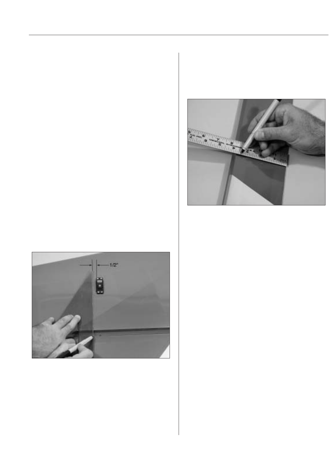
Step 1
Tape the aileron to the wing. Make a mark 1/2"
away from the edge of the servo towards the tip
of the wing. Using a square held in alignment (90°)
with the mark and with the trailing edge, mark the
aileron with a pen where the straight edge intersects
the aileron hinge bevel.
Step 2
Measure exactly 3
3
/
8
" forward from the trailing edge
of the aileron and make another mark using a felt-
tipped pen. The intersection of the line from Step 1
and this line will be the position for the control horn.
Step 3
Repeat Steps 1 and 2 for the second control
horn location.
Step 4
Remove the ailerons from the wing. Use rubbing
alcohol to remove any tape residue.
Step 5
Using a 5/32" drill bit and drill press, carefully drill
through the aileron at the marked position. Be
especially careful when penetrating through the top
surface of the aileron, as it’s easy to split out the
wood and rip the covering. Placing a wooden block
under the aileron and drilling slowly will prevent
these problems. If you choose to use the counter
sink screws included in the Hangar 9® Hardware
Package, counter sink the top of the aileron to allow
the screws to fit flush.