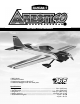
TM WE GET PEOPLE FLYING TM INSTRUCTION MANUAL • • • • 90% Prebuilt Hardware included Precovered in genuine UltraCote® Prefinished fiberglass cowl and wheel pants Specifications: • Wingspan: ........................................................................................................... 56 in (1422 mm) • Overall Length: ................................................................................................. 49 in (1245 mm) • Wing Area:................................................
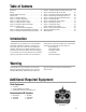
Table of Contents Introduction . . . . . . . . . . . . . . . . . . . . . . . . . . . . . . . . . . . . . . 3 Warning . . . . . . . . . . . . . . . . . . . . . . . . . . . . . . . . . . . . . . . . 3 Additional Required Equipment . . . . . . . . . . . . . . . . . . . . . . . 3 Contents of Kit . . . . . . . . . . . . . . . . . . . . . . . . . . . . . . . . . . . . 5 Section 1: Hinging the Ailerons . . . . . . . . . . . . . . . . . . . . . . . 6 Section 2: Joining the Wing Halves . . . . . . . . . . . . . . .
Engine Requirements • .40–.48 2-cycle engines • .56–.72 4-cycle engines Recommended 2-Cycle Engines • MDS™ .40 FS Pro • MDS .48 FS Pro • MDS .58 FS Pro Recommended 4-Cycle Engine MDS .48 • Saito .56 or .72 ™ Saito .
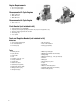
Contents of Kit Large Parts A F D H I E G B C A. Fuselage B. Left Wing Half with Aileron C. Right Wing Half with Aileron D. Vertical Stabilizer with Rudder E. Horizontal Stabilizer with Elevators (2) F. Cowl G. Canopy H. Wheel Pants I. Main Landing Gear Other Parts 6 5 3 4 7 1 2 1. Pushrod and Accessories 2. Plywood Die-Cut Parts (1/8") 3. Hardware Bag 4. Wheels 5. Fuel Tank and Hardware 6. Metal Motor Mount with Hardware 7.
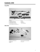
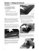
Section 1: Hinging the Ailerons Parts Needed • Right wing panel with aileron and hinges • Left wing panel with aileron and hinges Tools and Adhesives Needed • • • • Instant thin CA glue CA remover/debonder Paper towels T-pin (one for each hinge)(optional procedure) Note: All control surfaces are pre-hinged, however the hinges are not glued in place. It is imperative that you properly adhere the hinges and ailerons in place per the steps that follow using high-quality thin CA glue. Step 1.
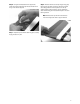
Step 6. Using CA remover/debonder and a paper towel, remove any excess CA glue that may have accumulated on the wing or in the aileron hinge area. Step 8. After both ailerons are securely hinged, firmly grasp the wing panel and aileron to check to make sure the hinges are securely glued and cannot be pulled out. Do this by carefully applying medium pressure, trying to separate the aileron from the wing panel. Use caution that you do not crush the wing structure.
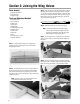
Section 2: Joining the Wing Halves Parts Needed • Right/left wing panels • Dihedral brace • Wing trim tape Tools and Adhesives Needed • 30-minute epoxy • 6-minute epoxy • Mixing stick • Epoxy brush • Masking tape • Hobby knife w/#11 blade • Rubbing alcohol • Paper towels • Wax paper • Ruler • Felt-tipped pen or pencil • Medium sandpaper Step 3. Place the wing on a large flat surface with the center of both wing panels resting on the flat surface.
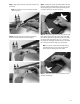
Step 7. Apply a generous amount of epoxy into the other wing panel cavity. Note: You may need to mix up more epoxy to complete the joining process. Step 8. Now apply epoxy to all sides of the exposed wing joiner and uniformly coat both wing roots with epoxy. Step 9. Carefully slide the two wing halves together and firmly press them together, allowing the excess epoxy to run out. There should not be any gap in the wing halves. Use rubbing alcohol and a paper towel to clean up any excess epoxy. Step 10.
Section 3: Installing the Aileron Servos Parts Needed • Assembled wing • Servos (JRPS537 or equivalent) (2) • Servo extensions (6" recommended) (2) • Y-harness (if using a non-computer radio) • String and a weight to run servo extensions through the wing Step 3. With the servo in place, mark the location of the servo screws used to mount the servo to the plywood servo rail inside the wing servo opening.
Step 6. Use a piece of string with a small weight (bolt from engine mounting hardware) attached as a device to attach to one end of the servo lead extension and thread through the servo opening through the wing and out the servo lead exit. Other methods can be used to thread the servo leads through the wing, but we have found this method is the quickest. Step 9. Repeat the procedure for the other wing half.
Section 4: Installing the Aileron Linkages Parts Needed • Assembled wing • Standard size servos with mounting hardware (2) • Servo extensions (6" or 9") (2) • Short rods, threaded on one end (2) • Clevis (2) • Wire keepers (2) • Control horn w/backplate (2) • Control horn mounting screws • Clevis keepers (2 pieces of fuel tubing 7mm long-not provided) Step 3. Thread a 2-56 clevis on the end of one of the threaded rods. Screw the clevis on 7-10 turns.
Step 5. Attach the control horn to the aileron using the screws and the control horn backplate. Be careful not to accidentally puncture the covering with the screwdriver. Step 6. With the linkage attached to the control horn, center the control surface and hold the linkage wire directly over the electronically centered servo arm. Place a mark on the rod directly over the hole (second hole from the end of arm) in servo control arm that it will connect to. Step 7.
Section 5: Mounting the Wing to the Fuselage Parts Needed • Wing • Fuselage • Wing hold-down bolt plate • Wing hold-down bolts and washers Tools and Adhesives Needed • 30-minute epoxy • Epoxy brush • Rubbing alcohol • Paper towels • Mixing sticks • Felt-tipped pen or pencil • Ruler • Drill • Drill Bit: 1/4" • Round file Step 3. When you’re satisfied the wing is centered, make a mark from the wing the center point to the fuselage where the trailing edge of the wing rests.
Step 5. Carefully install the wing back onto the fuselage without touching the wing bolt. Step 6. Hold the trailling edge over the bolt aligning the center of the wing over the mark you previously made on the wing. Carefully lower the trailling edge of the wing until it contacts the bolt. Gently press down on the trailling edge, to make an indentation on the bottom of the wing, marking where to drill for the wing bolt. Step 7. Remove the wing and the wing bolt from the fuselage.
Step 9. Locate the wing bolt hold-down plate. Note that the wing bolt hold-down plate has a hole already drilled for the wing bolt. Carefully remove the covering over the predrilled opening using a sharp hobby knife. Position on the wing, being sure to align the holes, and mark the location of the plate as shown. Step 11. Mix a small amount of 6-minute epoxy and epoxy the wing hold down plate to the wing. Allow the epoxy to cure completely before attempting the next step. Step 12.
Section 6: Installing the Tail (Vertical and Horizontal Stabilizer) Parts Needed • Horizontal stabilizer • Vertical stabilizer • Fuselage/wing assembly Step 3. Use a sharp hobby knife to remove the covering from the horizontal stabilizer slot in the fuselage.
Step 6. When you’re satisfied with the alignment of the horizontal stabilizer with the wing, carefully mark the position with a pencil at the junction where the horizontal stabilizer meets the fuselage. The pencil should leave a slight indentation in the covering. Step 10. Place the fuselage onto a flat surface and position the horizontal stabilizer onto it, making sure it’s centered and aligned as in Steps 4 and 5. Hint: Reference the bare wood you just exposed to re-align the stabilizer. Step 7.
Mounting the Vertical Stabilizer Step 12. Remove the rudder and hinges from the vertical stabilizer if you have not already done so. The rudder will be attached (hinged) to the vertical stabilizer later. Step 16. Mix approximately 1/2 ounce (minimum) of 30-minute epoxy and apply it to the vertical stabilizer where it comes into contact with the fuselage and horizontal stabilizer. Apply epoxy to the base of the vertical stabilizer where it touches the horizontal stabilizer. Step 13.
Section 7: Hinging the Horizontal Stabilizer and Elevators Parts Needed • Wing • Elevators (2) • Fuselage with vertical and horizontal stabilizers attached Step 3. After the hinges are dry, make sure they are securely in place by trying to pull the elevator from the horizontal stabilizer. Caution: Use care not to crush the structure. Tools and Adhesives Needed • Thin CA glue • CA remover/debonder • Paper towels • T-pins Step 1. Locate the elevators and hinges.
Section 8: Installing the Tail Wheel Assembly and Hinging the Rudder Parts Needed • Fuselage/wing assembly • Rudder • Hinges • Tail wheel • Tail wheel collar • Tail wheel assembly Step 3. Hold the tail wheel assembly up to the fuselage/rudder in a position where it’s flush with the fuselage bottom. Note where the wire and tail wheel nylon bearing rest in reference to the fuselage rear and the rudder.
Step 6. Use needle-nose pliers (or equivalent) to bend a 90-degree bend in the tail wheel wire. Remember it should be at a 90-degree angle to the axle of the tail wheel wire. A Zona keyhole saw and Dremel moto-tool can be used to open a slot at the rear of the fuselage for the nylon tailwheel bearing. Step 7. Trial fit the tail wheel assembly and rudder in place. Deflect the rudder, making sure the tail wheel assembly turns freely with the rudder. Step 8.
Section 9: Installing the Rudder and Elevator Control Horns Parts Needed • Control horns (3) • Control horn backplates (3) • Control horn screws (6) • Fuselage Step 2. Place the center of the control horn on the elevator at the mark made in the previous step. Mark the hole positions of the control horn with a felt-tipped pen or pencil.
Step 5. Repeat the preceding process for the other elevator half. Step 6. Measure 1/2" from the bottom of the left side of the rudder. Mark the location with a felt-tipped pen or pencil. This mark will serve as the center for the rudder control horn. Step 7. Center the control horn over the mark you’ve just made. Make sure the horn is positioned over the hinge line, just like you did for the elevator. Using a felt-tipped pen or pencil, mark the mounting hole locations onto the rudder. 24 Step 8.
Section 10: Installing the Main Landing Gear Parts Needed • Main landing gear (2 pieces) • Fuselage • Landing gear axles with lock nuts (2) • Wheel collar with screw (2) • Landing gear bolts (6) • Washers Step 2. Locate the six predrilled mounting holes in the bottom of the fuselage for mounting the landing gear. The blind nuts are preinstalled from inside the fuselage. If the covering is over the holes, use a sharp hobby knife and carefully remove the covering over the pre-drilled holes.
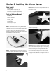
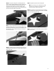
Section 11: Assembling and Mounting the Wheel Pants Parts Needed • Wheel pants • Wheels (2) • Main landing gear • Mounting hardware package Step 2. Locate the hole for the wheel axle 5/8" measured up from the bottom of the wheel pant centered on the mark made in Step 1. Mark with a felt-tipped pen or pencil. Repeat the procedure for the other wheel pant.
Step 5. Locate the axle, lock nut, wheel, and two wheel collars. Mount both axles to the landing gear using the large lock nuts. Step 6. The wheel pant can be trial fitted to the landing gear/axle. You may need to open up the large axle hole a bit with a round file, due to epoxy seeping into the opening Adjust the wheel pant in reference to the bottom of the fuselage so the bottom of the wheel pant is parallel to the bottom of the fuselage.
Section 12: Assembling and Installing the Fuel Tank Parts Needed • Clunk (fuel/pickup) • Tube (vent long) • Tube (fuel short) • Tube (fill short) (optional) • Fuel tank • Aluminum cap (large and small) • Stopper • Screw (3 mm) • Silicon tubing (2 green, 1 red) • Silicon tubing (clear, clunk) Step 3. Locate the other tube. This will be the vent tube. Bend one end up about 60 degrees but no more than 90 degrees. Caution: You can use your fingers to bend the tubing, but be careful not to kink the tubing.
Step 5. Locate the piece of silicone fuel tubing and metal clunk. This tubing will be attached to the clunk making up the fuel pickup inside the tank. Insert the metal clunk into one end of the fuel tubing. Step 8. Carefully insert the stopper into the fuel tank. Position the stopper so the vent tube is pointing to the top of the fuel tank. The vent tube must point to the top of the tank for the fuel system to function properly.
Section 13: Installing the Engine (2-Stroke/4-Stroke) Parts Needed • Fuselage • Engine • Engine mounting bracket (2) • Engine mounting screws, nuts, and washers (4 each) Tools and Adhesives Needed • Phillips screwdriver • Blue Locktite A-42 Step 1. Remove the two engine mounting brackets, four 4 x 20 mm screws, four washers, and four 4 mm nuts from the hardware package. Step 2. Position the engine on the motor mount.
Section 14: Installing the Radio Parts Needed • 4-channel radio system with 5 servos and hardware (not included) • Radio-packing foam (not included) • Antenna tube (optional, not included) Step 3. Once you are satisfied with the servo’s location, use a felt-tipped pen or pencil to mark the mounting holes for all three servos. Tools and Adhesives Needed • Drill • Drill Bit: 1/16" • Phillips screwdriver • Hobby knife with #11 blade • Felt-tipped pen or pencil Step 1.
Step 5. Use radio-packing foam (available at your local hobby shop) when you install the receiver and battery pack. There is ample room for the receiver and battery in the forward part of the fuselage, in the area above and behind the fuel tank. Wrap the battery and receiver securely in foam and install them into the fuselage. We suggest mounting the receiver on top of the battery pack using a rubber band to hold in place. Refer to the photos below. 32 Step 6.
Section 15: Installing the Control Linkages Parts Needed • Fuselage • Balsa dowels • Heat-shrink tubing • Threaded rod (1/16") (4) • Plain rod (1/16") • Nylon tube • Plastic clevis (4) • EZ Connector Step 3. Drill a 1/16" hole through the balsa dowels at the two marked positions, as shown below.
Step 6. Locate the following rods: two long threaded rods and one short non-threaded rod. These will be used to make up the elevator pushrod assembly. Step 7. Position the two long threaded rods so they are even at the threaded end and wrap in position on the dowel with masking tape. Mark each rod where it passes the holes drilled in the end of the dowel. Remove the rods and make a 90-degree bend in the unthreaded end where you made your marks. Step 8.
Step 13. Spread the two threaded pushrods apart (elevator pushrod) approximately 11/2" apart. Insert the elevator pushrod into the fuselage, threaded end first, so that the threaded rods come out of the elevator pushrod exits in the fuselage. Thread a nylon clevis on each rod 12-16 turns. Attach each clevis to an elevator control horn’s outermost hole. It’s a good idea to place a piece of fuel tubing (7 mm long) over each clevis to prevent the clevis from accidentally coming open in flight. Step 16.
Step 18. To install the throttle pushrod, locate the wire throttle pushrod and make a Z-bend at one end. This will be used to connect the carburator and to the throttle servo. Mount the engine and locate the point where the throttle linkage must exit the firewall to connect directly to the throttle arm on the carburator. Mark this point. Step 20. After drilling the hole in the firewall, slide the plastic tubing through the hole and secure in place with CA.
Section 16: Attaching the Cowling Parts Needed • Fuselage • Fiberglass cowl • Machine head screws (4) Tools and Adhesives Needed • Drill • Drill Bit: 1/16" • Masking tape • Moto-tool with sanding drum • Carbide cutter • Ruler • Sanding stick (medium) • Felt-tipped pen or pencil Step 1. Cut out a U-shaped opening in the bottom of the cowl. This will also allow for air flow around the cylinder. A template for the cowl opening is also provided. Step 3.
Step 7. Once the mounting holes have been marked, drill the holes on each side of the cowl using a 1/16" drill bit. Be sure to use masking tape to hold the cowl securely in position Step 8. Remove the cowling and enlarge the four holes in the cowling just enough to fit the rubber grommets in place. Note: On some engines where the carburetor is not easily accessible, a removable fueling valve can be used.
Section 17: Installing the Canopy Parts Needed • Assembled aircraft • Plastic canopy • Mounting screws (small) (4) • Trim tape Step 3. Trim as necessary to make for a good fit. When you’re satisfied with the fit, attach the canopy with canopy glue. Use masking tape to hold the canopy in place while the glue cures. Tools and Adhesives Needed • Sharp hobby knife • Scissors • Canopy glue (Pacer 560) • Phillips screwdriver Step 1. Locate the canopy. Step 2.
Section 18: Balancing the Aresti 40™ An extremely important step in preparing an aircraft for flight is ensuring it is properly balanced. Do not neglect this step. Each individual’s Aresti 40 will not be the same because of the various combinations of engines that can be used, servos, radio equipment, type of hardware used, and assembly methods used during building of the Aresti 40. Always check the center of gravity (CG) with the fuel tank empty.
AMA Safety Code 2001 Official AMA National Model Aircraft Safety Code Effective January 1, 2001 Model flying must be in accordance with this Code in order for AMA Liability Protection to apply. JATO use); also those items authorized for Air Show Team use as defined by AST Advisory Committee (document available from AMA HQ). In any case, models using rocket motors as primary means of propulsion are limited to a maximum weight of 3.3 pounds and a G series motor.
NOTES 42
© Copyright 2001, Horizon Hobby, Inc. (217) 355-9511 www.horizonhobby.