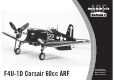
F4U-1D Corsair 60cc ARF Instruction Manual Bedienungsanleitung Manuel d’utilisation Manuale di Istruzioni 1
NOTICE All instructions, warranties and other collateral documents are subject to change at the sole discretion of Horizon Hobby, Inc. For up-to-date product literature, visit horizonhobby. com and click on the support tab for this product. SAFETY WARNINGS AND PRECAUTIONS SAFE OPERATING RECOMMENDATIONS Read and follow all instructions and safety precautions before use. Improper use can result in fire, serious injury and damage to property.
HINWEIS Alle Anweisungen, Garantien und anderen zugehörigen Dokumente können im eigenen Ermessen von Horizon Hobby, Inc. jederzeit geändert werden. Die aktuelle Produktliteratur finden Sie auf horizonhobby.com unter der Registerkarte „Support“ für das betreffende Produkt.
REMARQUE La totalité des instructions, garanties et autres documents est sujette à modification à la seule discrétion d’Horizon Hobby, Inc. Pour obtenir la documentation à jour, rendez-vous sur le site horizonhobby.com et cliquez sur l’onglet de support de ce produit.
AVVISO Tutte le istruzioni, le garanzie e gli altri documenti pertinenti sono soggetti a cambiamenti a totale discrezione di Horizon Hobby, Inc. Per una documentazione aggiornata sul prodotto, visitare il sito www.horizonhobby.com e fare clic sulla sezione Support per questo prodotto.
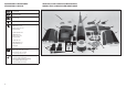
SPECIFICATIONS•SPEZIFIKATIONEN/ SPÉCIFICATIONS•SPECIFICHE LARGE PARTS LAYOUT•BAUTEILE (OHNE KLEINTEILE)/ GRANDES PIÈCES•SCHEMA DEI COMPONENTI GRANDI 85.5 in (217cm) 11 1380 sq in (89 dm2) 1 70.0 in (177cm) 6 9 16 28.5–31.0 lb (12.9–14.
REPLACEMENT PARTS•ERSATZTEILE•PIÈCES DE RECHANGE•RICAMBI Part English Deutsch Français Italiano 1. HAN476001 Fuselage with Fin Rumpf m. Seitenleitwerk Fuselage avec dérive Fusoliera con direzionale 2. HAN476002 Right Wing Panel with Aileron and Outer Flap Tragfläche rechts m. Querruder u. äußerer Klappe Aile droite avec aileron et volets Semiala destra con alettone e flap esterno 3. HAN476003 Left Wing Panel with Aileron and Outer Flap Tragfläche links m. Querruder u.
REQUIRED RADIO EQUIPMENT•ERFORDERLICHE RC AUSRÜSTUNG•EQUIPEMENT RADIO REQUIS•APPARECCHIATURE RADIO English Deutsch Français Italiano SPMAR9110 AR9110 9-Channel DSMX® PowerSafe™ Receiver Spektrum AR9110 9 Kanal DSM X Empfänger mit Akkuweiche Récepteur AR9110 9 voies DSMX PowerSafe Ricevitore AR9110 9-Canali DSMX PowerSafe SPMB2700NM (2) 2700mAh 6.0V NiMH Receiver Pack 2700mAh 6.0V NiMH Empfänger Akku Batterie de réception Ni-Mh 6V 2700mA 2700mAh 6.
4-STROKE GAS•4 TAKT BENZINER•4 TEMPS ESSENCE•4-TEMPI A BENZINA English Deutsch Français Italiano SAIEG57T 57cc Gas Twin Engine 4-Stroke 57cc Benzin Zweizylinder 4 Takt Motor Moteur Bicylindre 4 temps essence 57cc 57cc Motore a benzina 4 tempi SPM9530 Spektrum™ 3-Wire Switch Harness Spektrum Schalterkabel 3 Anschlüsse Interrupteur Spektrum Spektrum Interruttore a 3 fili VSS2202 22 inch Diameter Gas-Series Propeller, B-Pitch 22 inch Durchmesser Gas-Series Propeller, B-Pitch Hélice 22’ pour mot
ELECTRIC RETRACTS•ELEKTRISCHES EINZIEHFAHRWERK•TRAIN RENTRANT ÉLECTRIQUE•RETRATTILI ELETTRICI English Deutsch Français Italiano HAN476026 Robart Retractable Main Gear (Elec): F4U-1D Corsair 60cc Hangar 9 F4U-1D Corsair 60cc: Robart Hauptfahrwerk (Elektr.) Train rentrant principal Robart électrique Carrello retrattile principale Robart (Elec) F4U-1D Corsair 60cc HAN476028 Robart Tail Wheel Electric Actuator: F4U-1D Corsair 60cc Hangar 9 F4U-1D Corsair 60cc: Robart E-Antrieb f.
OPTIONAL PAYLOAD RELEASE•OPTIONALES NUTZLASTABWURFSYSTEM•DISPOSITIF DE LARGAGE OPTIONNEL•SGANCIO CARICHI OPZIONALE English Deutsch Français Italiano EFLA405 (2) Servoless Payload Release E-flite Servoloses Nutzlastabwurfsystem Dispositif de largage sans servo Sgancio carichi senza servo SPMA3001 Heavy-Duty Servo Extension 6 inch Spektrum Hochleistungs Servokabelverlängerung 150 mm Rallonge de servo 150 mm Prolunga servo HD 150 mm SPMA3004 Heavy-Duty Servo Extension 18 inch Spektrum Hochleistu
REQUIRED TOOLS•BENÖTIGTES WERKZEUG•OUTILS REQUIS•ATTREZZI NECESSARI English Deutsch Français Italiano Hemostat Klemme Pince Hemostat Pinzetta Hex wrench: .050 inch, 3/32 inch, 3/16 inch, 5/32 inch, 4mm, 5mm Inbusschlüssel: .050 inch, 3/32 inch, 3/16 inch, 5/32 inch, 4mm, 5mm Tournevis hexagonal: .050 inch, 3/32 inch, 3/16 inch, 5/32 inch, 4mm, 5mm Chiave esag.: .
BEFORE STARTING ASSEMBLY VOR DEM ZUSAMMENBAU AVANT DE COMMENCER L’ASSEMBLAGE PRIMA DI INIZIARE IL MONTAGGIO • Remove parts from bag. • Entnehmen Sie zur Überprüfung jedes Teil der Verpackung. • Retirez toutes les pièces des sachets pour les inspecter. • Togliere tutti i pezzi dalla scatola. • Inspect fuselage, wing panels, rudder and stabilizer for damage. • Überprüfen Sie den Rumpf, Tragflächen, Seiten- und Höhenruder auf Beschädigung.
FASTENERS•VERBINDUNGSELEMENTE•ATTACHES•ELEMENTI DI FISSAGGIO Flat Washer Unterlegscheibe Rondelle plate Rondella piatta 14 Lock Nut Stopmutter Ecrou auto-freiné Dado di bloccaggio Self-Tapping Screw Selbstschneidene Schraube Vis auto-taraudeuse Vite autofilettante Nylon Clevis Nylon Gabelkopf Chape nylon Cambra di nylon Self-Tapping Washer-Head Screw Schraube mit Unterlegscheibenkopf Vis auto-taraudeuse épaulée Vite autofilettante flangiata Control horn Ruderhorn Guignol de commande Squadretta di cont
ASSEMBLY SYMBOL GUIDE•MONTAGE SYMBOLE•GUIDE DES SYMBOLES POUR ASSEMBLAGE•GUIDA AI SIMBOLI DI ASSEMBLAGGIO Apply threadlock Ensure free rotation Use medium CA Use a pencil Schraubensicherungslack verwenden Rotation sicherstellen Verwenden Sie einen Bleistift Utilisez du frein filet Permettez une rotation libre Mittelflüssigen Sekundenkleber verwenden Applicare fuido threadlock Utilisez de la colle cyanoacrylate moyenne Assicurarsi rotazione libera Utilisez un crayon à papier Usare una matita Usar
JOINING THE WING PANELS•VERKLEBEN DER TRAGFLÄCHEN•ASSEMBLAGE DE L’AILE•UNIRE LE SEMIALI 1 2 3 LL RR LL RR LL RR Move the string located in the center section and tip panels so they will not interfere with the fit of the tip panels to the center section. Use tape to mark the aileron and flap panels with right or left so they can be relocated to their correct locations. Slide the wing joiner into the tip panel. Mark the joiner to indicate how far in the joiner fits in the tip panel.
5 LL RR 6 OIL Separate the tip panel from the center section. Apply a coating of petroleum jelly to the area around the joiner pocket so when the tip panel is fit to the center section in the next steps it won’t be accidentally glued together. Nehmen Sie die Tragflächen wieder auseinander. Geben Sie ein Schicht Vaseline um die Verbinderöffnung am Mittelteil, so dass diese nicht aus Versehen geklebt werden kann. Séparez l’aile de la section centrale.
9 AILERON SERVO INSTALLATION•EINBAU DER QUERRUDERSERVOS• INSTALLATION DES SERVOS D’AILERONS•INSTALLAZIONE SERVO ALETTONI 1 2 LL RR LL RR 1/4-20 x 1.5 inch x2 Fit the tip panel and center section together. Use the 1/4-20 x 1.5-inch nylon bolt to hold the tip and center section together until the epoxy fully cures. Schieben Sie Aussen- und Mittelteil zusammen. Schrauben Sie die Fläche mit den 1/4 x 20 x 1,5 Inch Nylonschrauben zusammen bis der Klebstoff vollständig getrocknet ist.
4 LL RR Apply a small amount of thin CA to harden the threads made in the previous step. Geben Sie einen kleinen Tropfen dünnflüssigen Sekundenkleber in die Gewindelöcher um diese zu härten. Appliquez une petite quantité de colle cyano fine pour durcir les filetages faits lors de l’étape précédente. Mettere una piccola quantità di colla CA nei fori, per indurire il filetto fatto nel passaggio precedente. 5 Prepare the aileron servos by installing the grommets and brass eyelets.
7 8 AILERON PREPARATION•QUERRUDERVORBEREITUNG• PRÉPARATION DES AILERONS•PREPARAZIONE DEGLI ALETTONI 1 2 Top• Oberseite•Dessus•Sopra LL RR M3 x 10 x6 Secure the aileron servo into position using the black M3 x 10 washer head screws. The arrows indicate the location of the leading edge (1) and wing tip (2). LL RR Bottom• Unterseite•Dessous•Sotto Schrauben Sie die Querruderservoabdeckung mit den sechs schwarzen M2 x 10 Schrauben fest.
3 4 5 x6 LL RR x3 Apply a small amount of petroleum jelly to the flex point of the hinge to prevent epoxy from entering the hinge. Geben Sie etwas Vaseline auf das Gelenk des Scharnieres damit es nicht verklebt. Appliquez une petite quantité de gelée de pétrole au niveau du pivot de la charnière pour éviter le blocage de la charnière par la colle époxy. Mettere una piccola quantità di vaselina sullo snodo della cerniera per evitare che la colla la blocchi. Insert the hinges into the ailerons.
7 8 FLAP HINGING• ANSCHLAGEN DER KLAPPEN• ARTICULATION DES VOLETS• INCERNIERARE I FLAP 1 LL RR LL RR Fit the aileron to the wing. There will be a gap of 1/32 to 1/16 inch (1 to 1.5mm) between the aileron leading edge and wing inner hinge surface. Check to make sure the aileron can move without binding. DO NOT glue the hinges at this time. Passen Sie das Querruder an die Tragfläche an. Zwischen Aussen- und Innenseite sollte ein Spalt von 1 bis 1,5 mm sein.
2 LL RR Fit the inner and center flap together. The joiner blade may bind slightly. Stecken Sie innere und mittlere Klappe zusammen. Der Verbinder könnte dabei etwas klemmen. 3 4 LL RR x12 If you find the joiner blade binding, carefully trim or sand the slot until the joiner blade can move freely inside the flap. Also check the fit between the center flap and outer flap at this time. The fit between the joiner and joiner pocket should allow for smooth movement, but should not be loose.
5 6 LL RR 7 8 LL RR LL RR Insert the hinges into the flap panels until the line drawn in the previous step is aligned with the leading edge of the flap. Check the angle of the hinges in relationship to the flap center line. They will be perpendicular for the inner and outer flaps. Stecken Sie die Scharniere bis zur Markierung ein die Sie letzten Schritt gemacht haben. Überprüfen Sie den Winkel der Scharniere in Verhältnis zur Klappenmittellinie.
9 LL RR OIL 10 11 LL RR LL RR Use sandpaper to lightly sand the flap control rod where it will be glued into the flap. Also apply a small amount of petroleum jelly where the joiner wire will ride in the center section of the wing. Insert the control rod in the center section. Make sure the flat area on the joiner wire faces up and away from the wing. The bevel should lean forward when the joiner is in the up position. Fit the inner, center and outer flap to the wing and center section.
12 13 14 LL RR LL RR LL RR Check the operation of the flap, using care not to move the hinges from their locations. When positioned correctly, you will be able to achieve the throws listed in the Control Throw section of this manual. Prüfen Sie den Weg der Klappen und achten dabei darauf die Scharniere nicht aus ihren Positionen zu bewegen. Haben Sie die Klappen richtig positioniert werden diese die in der Anleitung angebenden Ausschläge erreichen.
15 16 LL RR LL RR 30 Begin by placing the outer flap and aileron in position WITHOUT the use of epoxy. This will aid in the alignment of the remaining flap sections. Apply epoxy to the flap torque rod and flap hinges. Place the flaps into position and allow the epoxy to fully cure before proceeding, making sure to maintain the alignment of the flaps so they will operate correctly when the linkage is installed. Beginnen Sie die äußeren Klappen und die Querruder ohne Epoxy in Position zu setzen.
FLAP SERVO INSTALLATION•EINBAU DER KLAPPENSERVOS•INSTALLATION DES SERVOS DE VOLETS•INSTALLAZIONE DEL SERVO DEI FLAP 1 2 Move the string inside the center section so the flap servo can be installed. Use a rotary tool and cut-off wheel to trim the aluminum control horn so only the inner hole remains. With the flap servo centered, attach the horn to the flap servo. 3 4 M3 x 10 Bewegen Sie die Schnur in das Mittelteil, so dass Sie das Klappenservo einbauen können.
5 x2 x1 Remove the links from two of the control horns. Assemble the flap linkage using the ball ends on the single side and the swivel links on the dual end that are included with the model. Nehmen Sie die Anlekungen von zwei Ruderhörnern ab. Montieren Sie die Klappenanlenkung mit den Kugelköpfen auf der einen Seite und dem gedrehten Ende auf der anderen Seite aus dem Lieferumfang des Modells. 6 8 Attach the ball end to the flap servo arm. Attach the flap control horns to the flap torque rods.
9 Connect the ball end to the flap control horns. Adjust the length of the linkage so the flaps are up when the servo is in the UP FLAP position. Schließen Sie die Kugelköpfe an die Klappenhörner an. Stellen Sie die Länge des Gestänges so ein, dass die Klappen eingefahren sind wenn das Servo in Position Klappen eingefahren ist. Connectez les rotules aux guignols. Ajustez la longueur de la tringlerie pour que les volets se positionnent en position haute quand le servo est en position haute.
4 RETRACT INSTALLATION•EINBAU DES EINZIEHFAHRWERKES•INSTALLATION DU TRAIN RENTRANT•INSTALLAZIONE DEI RETRATTILI 1 LL RR With the radio system on and the aileron servo centered, adjust the length of the aileron linkage to center the aileron. Once centered, tighten the nut against the clevis to keep if from vibrating and changing position. Justieren Sie mit eingeschalteter Fernsteuerung und zentriertem Servo die Länge der Anlenkung.
OPTIONAL WHEELS•OPTIONALE RÄDER•ROUES OPTIONNELLES•RUOTE OPZIONALI 4 LL RR LL RR Adding the optional powder-coated aluminum wheels will enhance the look and handling of your model. The installation of the optional wheels follows the same procedure as the included wheels. Verbessern Sie das Aussehen und das Handling mit den optionalen pulverbeschichteten Aluminiumrädern. Die Montage erfolgt in gleicher Weise wie bei den Rädern im Lieferumfang.
6 7 8 LL RR LL RR Once the retract has been positioned, remove it from the wing and attach two 18-inch (457mm) pieces of air line to the retract. Use the instructions included with the retract to colorcode the air line installation. Slide the air line at the rear of the retract through the predrilled hole in the spar. Carefully fit the retract (and shims) into the wing without pulling the air line at the front out of position.
10 11 12 LANDING GEAR DOOR INSTALLATION• EINBAU DER FAHRWERKSTÜREN• INSTALLATION DES TRAPPES DE TRAIN• INSTALLARE IL PORTELLO DEL CARRELLO 1 LL RR Secure the retract mechanism in position. Schrauben Sie das Einzíehfahrwerk ein. Fixez le mécanisme en position. Fissare il meccanismo del retrattile al suo posto. LL RR Tape the rear air line and a 18-inch (460 mm) servo extension to the string pre-installed in the center section.
2 3 4 LL RR x4 LL RR Sand both the stops and the underside of the cover before gluing them together. Use medium CA to glue the stops to the underside of the covers, using the embossed lines to properly position the stops. Schleifen Sie die Stopper und die Unterseite der Abdeckung an bevor Sie diese verkleben. Verwenden Sie mittleren Sekundenkleber und nutzen sie die erhabenen Linien um die Stopper richtig zu positionieren.
6 LL RR 7 M2 x 10 x6 Tape the cover to the wing using low-tack tape. Use a drill and 1/32-inch (1mm) drill bit to drill the six holes to mount the cover to the wing. Lift the cover and enlarge the holes in the cover ONLY using a pin vise and 1/16-inch (1.5mm) drill bit. Secure the cover to the wing using the specified screws. Kleben Sie die Abdeckung mit Klebeband mit geringer Klebkraft ein und bohren mit einem 1mm Bohrer die sechs Befestigungslöcher.
10 11 12 13 LL RR LL RR LL RR LL RR With the cover and door removed, remove the clear tape. Use medium CA to glue the hinges to the door. Make sure to prepare the hinges and door before gluing to ensure a good bond between the two. With the gear in the DOWN position, mark the gear door for the location for the rubber band that will connect the door to the strut. Make sure to mark the gear door just above the rotational strut.
14 15 LL RR LL RR Tape the gear door to the wing using low-tack tape. Use a drill and 1/32-inch (1mm) drill bit to drill the six holes to mount the gear door to the wing. Lift the gear door and enlarge the holes in the gear door ONLY using a pin vise and 1/16-inch (1.5mm) drill bit. Kleben Sie die Tür mit Klebeband mit geringer Klebkraft fest. Bohren Sie mit einem 1mm Bohrer die sechs Löcher für die Fahrwerkstür in die Tragfläche.
The main gear doors can be made operational using the hardware listed at the beginning of the manual. Mounts for the hinges and servos will require fabrication by the modeler. Use the photos as a reference to modify your model to install the operational gear doors. A template has been provided to assist in making the servo mounting plate for the gear door servo on page 94.
4 5 6 M3 x 10 Cut and place a second piece of foam, placing it on the first battery. Insert the second receiver battery, then secure the batteries using the hook and loop straps. Schneiden Sie ein zweites Stück Schaumstoff zurecht und plazieren es auf dem ersten Akku. Legen Sie den zweite Akku darauf und sichern beide mit der Klettschlaufe. Coupez un second morceau de mousse et placez-le sur la première batterie.
RUDDER AND ELEVATOR SERVO INSTALLATION•EINBAU VON HÖHEN UND SEITENRUDERSERVO•INSTALLATION DES SERVOS DE PROFONDEUR ET DE DÉRIVE•INSTALLAZIONE SERVI TIMONE ED ELEVATORE AIR TANK AND RECEIVER INSTALLATION•EINBAU DES DRUCKLUFTTANK UND DES EMPFÄNGERS• INSTALLATION DU RÉSERVOIR D’AIR ET DU RÉCEPTEUR•INSTALLAZIONE DEL RICEVITORE E DEL SERBATOIO PER L’ARIA 1 2 3 1 Use a pin vise and 1/16-inch (1.5mm) drill bit to enlarge the holes for the rudder (center) and elevator (outer) servo mounting screws.
4 #4 5 6 Remove the covering from the side of the fuselage for the switch mount. Secure the switch in the side of the fuselage using the hardware provided with the switch. Connect the leads for the rudder and elevator servos. Connect a 6-inch (150 mm) lead for the aileron and flap servos. A 12-inch (300 mm) lead will be required for connection to the throttle servo. Finally, connect a 12-inch (300 mm) extension to the data port to allow access to the receiver for binding.
7B (ELECTRIC RETRACT INSTALLATION• EINBAU DES ELEKTRISCHEN FAHRWERKES•(INSTALLATION DU TRAIN RENTRANT ÉLECTRIQUE) •INSTALLAZIONE RETRATTILI ELETTRICI) Fabricate a support for the front of the receiver tray using the material from an unused engine mounting template. Mount the receiver in the fuselage. Route the leads for the ailerons and flaps, as well as the throttle servo, through the fuselage. Fertigen Sie aus einer ungenutzten Motorschablone einen Halter für das vordere Ende des Empfängerbrettchen.
RUDDER INSTALLATION•EINBAU DES SEITENRUDERS•INSTALLATION DE LA GOUVERNE DE DÉRIVE•INSTALLAZIONE DEL TIMONE 1 30 2 x2 x2 Remove the covering for the rudder torque rod. Apply a small amount of petroleum jelly to the flex point of the hinge to prevent epoxy from entering the hinge. Insert the hinges into the rudder. Use the depth gauges marked R1 and R2 to make sure the hinges fit into the rudder.
4 5 RUDDER LINKAGE INSTALLATION•EINBAU DER RUDERANLENKUNG• INSTALLATION DE LA TRINGLERIE DE LA DÉRIVE•INSTALLAZIONE DEL COMANDO TIMONE 1 Fit the rudder to the fin, guiding the torque rod into the fuselage. Make sure the rudder torque rod is inserted through the hole in the former for support. Once fit, remove the rudder and use epoxy on the hinges and in the hinge pocket to secure the rudder to the fin.
2 3 Slide the collar on the rudder torque rod. Tighten the bolt using a 9/32-inch (7mm) open end wrench. The control horn will not rotate and will be against the head of the bolt once the control horn is secure. Thread the ball link on the 393/4-inch (1010mm) pushrod. Schieben Sie den Stellring auf den Ruderstift. Ziehen Sie die Schraube mit einem 7mm Gabelschlüssel an. Das Ruderhorn wird sich dabei nicht mitdrehen und bei gesicherten Stellring wieder am Schraubenkopf sein.
6 7 x1 Attach the 4-40 ball end to the control horn on the end that aligns with the rudder pushrod. Schrauben Sie den 4.40 Kugelkopfanschluß wie abgebildet auf das Ruderhorn. Fixez une chape à rotule sur le palonnier de façon à l’aligner avec la tringlerie de dérive. Attaccare la sfera 4-40 alla squadretta dalla parte allineata al comando del timone. Thread the ball end on the rudder pushrod. With the rudder servo centered, place the horn on the rudder servo.
3 4 5 6 Check alignment Ausrichtung überprüfen Slide the stabilizer on the tubes. The stabilizer will fit tightly against the fuselage. Install both stabilizer halves at this time. Schieben Sie beide Leitwerksseiten auf die Verbinder. Das Leitwerk paßt sauber an den Rumpf. Glissez les deux parties du stabilisateur sur les clés. Les deux parties du stabilisateur doivent parfaitement s’ajuster contre le fuselage. Inserire lo stabilizzatore sui tubetti in modo che sia contro alla fusoliera.
7 Remove the stabilizers and verify that the tubes are centered in the fuselage. If the joiner tubes slide while gluing the stabilizer, wrap a piece of low-tack tape around one end of the tube so they can be easily repositioned. Nehmen Sie das Leitwerk ab und überprüfen dass die Verbinder zentriert sind. Sollten sich die Verbinder während des Verklebens bewegen kleben sie um ein Ende etwas Klebeband mit geringer Klebkraft, so dass sie einfach positioniert werden können.
ELEVATOR INSTALLATION•EINBAU DES HÖHENRUDERS•INSTALLATION DE LA GOUVERNE DE PROFONDEUR•INSTALLAZIONE DELL’ELEVATORE 1 2 x3 3 LL RR Position the hinge perpendicular to the hinge line. Check that it can move freely. Richten Sie das Scharnier rechtwinklig zur Scharnierlinie aus. Prüfen Sie dass es sich frei bewegen kann. Positionner la charnière perpendiculairement à la ligne de la charnière. Contrôler la liberté de mouvement.
4 LL RR 5 x2 Thread the control horn on the elevator torque rod. Note that the head of the screw is facing toward the tip of the elevator. The top of the control horn is flush with the top of the torque rod. Drehen Sie ein Ruderhorn auf den Ruderstift. Bitte beachten Sie dass der Kopf der Schraube nach hinten und der Gestängeanschluß nach vorne zeigt. Die Oberkante des Anschlusses muß bündig mit der Schraube abschließen. Vissez la tête du bras de commande sur la tige.
9 10 11 LL RR LL RR With the elevator and elevator servo centered, mark the pushrod at the edge of the ball link. This will help when threading the ball link on the pushrod. Markieren Sie mit zentriertem Höhenruder und Servo das Gestänge am Anschluss. Dieses hilft bei dem Aufdrehen des Kugelkopfes. LL RR Slide the elevator pushrod into the pushrod tubes. It is easiest to start outside the fuselage as the angle from the wing saddle will not allow for this installation.
13 PNEUMATIC RETRACT SERVO INSTALLATION•EINBAU DES PNEUMATISCHEN EINZIEHFAHRWERKSERVOS• INSTALLATION DU SERVO DE COMMANDE DU TRAIN RENTRANT PNEUMATIQUE•INSTALLAZIONE DEL SERVO PER CARRELLO AD ARIA 1 2 3 #2 #2 x 1/2 x2 x2 Thread a screw into each of the holes to cut threads into the surrounding wood. Remove the screw before proceeding. Apply a small amount of thin CA to harden the threads made in the previous step. Attach the tail cone to the fuselage.
4 5 6 7 Prepare the connectors for the retract valve by attaching a 6-inch (152mm) piece of tubing to the connectors. Make sure to match the ail line fittings and color coding to match the air lines in the wing. Connect a 1-inch (25mm) piece of tubing to the lines that will actuate the retracts at the valve. Connect a t-fitting to the tubes at the valves, then attach the air lines and fittings prepared in the previous step. Bereiten Sie die Anschlüsse mit 152mm langen Schlauch vor.
8 TAIL WHEEL INSTALLATION•EINBAU DES SPORNRADES• INSTALLATION DE LA ROULETTE DE QUEUE•INSTALLAZIONE DEL RUOTINO DI CODA 1 2 3 LL RR LL RR Lower the retract servo assembly into the fuselage. Connect the air line from the air tank to the valve. Plug the servo into the retract port of the receiver. Use medium CA to glue the retract servo mount inside the fuselage. Cut the tail wheel cable into two equal lengths.
5 LL RR 6 4-40 M x2 x2 x2 Slide the heat shrink on the cable. Thread a nut on the cable end, then slide a silicone retainer on the clevis. Thread the clevis on the cable end. Schieben Sie den Schrumpfschlauf auf das Kabel. Drehen Sie eine Mutter auf das Kabel uns setzen den Silikonschlauch auf den Gabelkopf. Drehen Sie den Gabelkopf auf den Augenbolzen. Glissez un des morceaux de gaine thermo-rétractable.
10 Temporarily install the retract assembly into the fuselage. The assembly will be secured once the length of the retract actuator pushrod has been set. Setzen Sie die Mechanik vorübergehend in den Rumpf ein. Diese wird erst dann festgeschraubt wenn die Gestängelänge eingestellt ist. Installez temporairement le mécanisme dans le fuselage. Le mécanisme sera fixé une fois que la longueur de la tringlerie de commande sera réglée. Posizionare temporaneamente in fusoliera il gruppo del retrattile.
13 15 14 #4 Replace the pin and clip to attach the actuator to the mount. Setzen Sie den Pin und Clip wieder auf um den Geber in den Halter zu setzen. Replacez l’axe et le clip pour fixer l’actionneur à son support. Sostituire il perno e la clip per attaccare l’attuatore al supporto. 4-40 x 1/2-inch x6 x6 Install the screws that secure the retract assembly in the fuselage. Start with the screws inside the fuselage, working outward to maintain the alignment of the assembly.
17 18 (OPTIONAL•OPTIONAL• FACULTATIF•FACOLTATIVO) SCALE EXHAUST INSTALLATION• EINBAU DER SCALE AUSPUFFANLAGE• INSTALLATION DES SORTIES D’ÉCHAPPEMENT MAQUETTE• INSTALLAZIONE SCARICO IN SCALA 1 M2 x 8 x6 Carefully trim the tail gear door to fit the tail wheel retract. Make sure the retract can move without hitting the door. Once the door has been trimmed, tape the tail gear door to the fuselage using low-tack tape.
2 ENGINE INSTALLATION (G62)•MOTOREINBAU (G62)•INSTALLATION DU MOTEUR (G62)•INSTALLAZIONE DEL MOTORE (G62) 1 LL RR M3 3 Remove the template from the firewall. Use a drill and 5/16inch (8mm) drill bit to enlarge the holes in the firewall. Use a rotary tool and sanding drum to enlarge the opening in the fuselage if you are using the optional spring starter on your engine. Make an area for the fuel lines to clear the spring starter so they are not damaged by the rotating starter.
4 #4 1/4-20 x 11/4 inch x1 x1 5 6 7 Examine the fuel tank to determine where the fuel lines attach inside the tank. Mark the fuel lines so they can be identified when the fuel tank is installed inside the fuselage. Place two tie wraps through the fuel tank mounting plate. Use care not to loop the tie wraps through any wiring or formers near the mounting plate. Secure the fuel tank inside the fuselage using the tie wraps.
8 9 10 1/4-20 x 11/4 inch Install the optional spring starter and mount on the engine. Use the instructions included with these accessories for their installation. Montieren Sie den optionalen Federstarter und den Motor. Lesen Sie dazu bitte die dazugehörigen Anweisungen. Installez le ressort de démarrage optionnel et le bâtit sur le moteur. Suivez les instructions fournies avec ces éléments pour effectuer leur installation. Installare la molla di avviamento opzionale e installare il motore.
12 13 14 x1 Use a pin vise and 1/16-inch (1.5mm) drill bit to enlarge the holes for the throttle servo mounting screws. Thread a servo mounting screw into each of the holes to cut threads in the surrounding wood. Remove the screw, then apply a small amount of thin CA to harden the threads. Secure the throttle servo in the fuselage. With the radio system on, move the stick to low throttle. Fit the large servo arm (not included) on the servo so it almost touches the exhaust port.
15 16 17 Route the vent line from the fuel tank to the bottom of the fuselage. A fuel dot was mounted in the scale exhaust for the vent line to prevent it from interfering with the operation of the engine. Connect the line from the clunk to the carburetor. Use a fuel filter near the carburetor to prevent debris in the fuel from entering the engine. Also use a fuel dot mounted in the scale exhaust to access the fuel line when the cowl is installed.
18B (SAITO FG57) COWLING INSTALLATION•MONTAGE DER MOTORHAUBE•INSTALLATION DU CAPOT•INSTALLAZIONE DELLA CAPOTTINA MOTORE 1 2 3 Locate the cowling. Note that the top of the cowling is indented, while the bottom is completely round. Fit the cowling to the engine. Carefully trim the cowling to clear the muffler, spark plug or any other items that require access from outside the cowling. Cut and trim the forward portion of the engine to fit over the engine drive washer.
5 4 #4 Glue the scale engine inside the cowling using silicone adhesive. Kleben Sie die Motorattrappe mit Silikonklebstoff in die Motorhaube. Collez le faux-moteur à l’intérieur du capot en utilisant de la colle silicone. Incollare il finto motore all’interno della capottina con silicone adesivo. Î The scale engine is not required when using the engine shown in this manual. Some engines may require the use of the scale engine as a baffle to reduce the amount of air entering the cowling for cooling.
7 8 Secure the propeller to the engine using the recommended spinner adapter. Use a box wrench to tighten the propeller bolt. Secure the spinner in position on the engine. Schrauben Sie den Propeller mit dem empfohlenen Adapter an. Ziehen Sie die Mutter mit einem Ringschlüssel fest. Fixez le cône en position. Fixez l’hélice au moteur en utilisant l’adaptateur recommandé. Utilisez une clé plate fermée pour serrer l’écrou de fixation d’hélice.
3 4 5 Use hobby scissors to trim the instrument panel. Trim the instrument panel decal and apply it to the instrument panel. Schneiden Sie mit einer Schere das Instrumentenbrett zurecht. Schneiden Sie die Instrumentenaufkleber aus und kleben diese auf das Instrumentenbrett. Utilisez des ciseaux à lexan pour découper le tableau de bord. Découpez l’adhésif des instruments et appliquez-le sur le tableau de bord.
6 7 Î Additional detail can be added to the cockpit using a variety of items including, but not limited to paint,chalk, pins, etc. Use the following images to help in detailing the cockpit. Î Eine höhere Detaillierung kann auf verschiedenen Wegen erreicht werden. Zusätzliche Farbe oder etwas Kreide als Alterung oder kleine Knöpfe im Cockpit sind nur einige der vielen Möglichkeiten. Nutzen Sie die Bilder unten als Hilfestellung.
SLIDING CANOPY INSTALLATION•EINBAU DER COCKPITÖFFNUNG•INSTALLATION DE LA VERRIÈRE COULISSANTE•INSTALLAZIONE DELLA CAPOTTINA SCORREVOLE Î The model comes with a sliding canopy. This has been tested with all of the suggested motors in this manual. The fit and installation of the front and back sections of the canopy are crucial to its correct operation. If a sliding canopy is not wanted, a solid canopy is available for purchase.
4 5 6 7 Check the fit of the forward and rear canopy pieces. They must fit together tightly. If not, lightly sand the face of the frame to compensate for any gaps between the forward and rear canopies. Trim the covering from the sides of the fuselage to expose the slide rail for the canopy slides. Apply one layer of tape toward the front of the rails. The tape should be just above and below the rails’ openings. Mark the aft location of the larger opening for the sliders.
8 Install the rear canopy on the front rails. Fit the rear canopy so that it is all the way forward in the front tracks. Setzen Sie die hintere Kabinenhaube auf die vorderen Schienen. Passen Sie die hintere Kabinenhaube so an, dass sie ganz vorne ist. Installez la partie arrière de la verrière sur les rails avant. Positionnez la verrière le plus en avant possible sur les rails. Inserire la capottina posteriore nelle guide anteriori e portarla completamente in avanti.
12 OPTIONAL SOLID CANOPY INSTALLATION• OPTIONALER EINBAU DER FIXEN KABINENHAUBE• INSTALLATION DE LA VERRIÈRE FIXE OPTIONNELLE• INSTALLAZIONE CAPOTTINA FISSA OPZIONALE SCALE ACCESSORIES•SCALE ACCESSORIES• ACCESSOIRES MAQUETTE•ACCESSORI IN SCALA 1 2 1 After all glue is dry. Slide the rear sliders forward a small amount, bowing the sides of the canopy a small amount. This will allow the rear sliders to come back out of the tracks so the forward sliders can slide back and be removed.
3 4 5 6 Use hobby scissors to trim the three guns from the molded gun set. Fit the guns to the wing. Trim the wing as necessary to fit the guns flush with the leading edge of the wing. Use canopy glue to glue the guns in position. Use low-tack tape to hold the guns in position until the glue fully cures. Attach the stall strip to the wing panel using canopy glue. The stall strip is located 40mm from the outboard gun on the right wing tip panel.
OPTIONAL LIGHTING•OPTIONALE BELEUCHTUNG•ECLAIRAGES OPTIONNELS•LUCI OPZIONALI 1 3 5 4 Secure the lighting controller inside the fuselage. Connect the controller to an open port on the receiver to power and actuate the lights using the radio system. Connect an 18-inch (450 mm) lighting extension to two of the leads from the controller to connect to the extension that will be located in the wing center section.
ORDINANCE INSTALLATION•ANBAU DER AUSSENLASTEN•INSTALLATION DES PYLÔNES•INSTALLAZIONE DEGLI ORDIGNI 1 2 3 Use a ruler to connect the lines at the front and rear of the center section. This will be used as a reference when placing the ordinance mounts. Place low-tack tape along the centerline of the center section. Kleben Sie wie abgebildet Klebeband mit geringer Klebekraft auf den Mittelbereich des Tragflächenmittelstückes. Placez de l’adhésif de masquage sur la ligne centrale de l’aile.
5 6 7 8 LL RR LL RR LL RR LL RR Place low-tack tape on the bottom of the center section as shown. Using a ruler, place a mark at the front and rear 6 11/16 inches (170mm) from the centerline. Connect the marks to create a reference line for mounting the ordinance pylon. This line will be parallel to the centerline on the bottom of the wing. Place a ruler so it is resting flat on the front of the center section.
9 10 11 12 LL RR LL RR LL RR LL RR Position the pylon on the bottom of the wing using the marks made as reference. Align the front of the pylon with the mark made 4 7/8 inches (123mm) back from the front of the wing. Mark the locations for the rear mounting screw and servo lead on the tape. Setzen Sie den Halter auf die Tragfläche. Richten Sie die Vorderseite an der 123mm Markierung aus. Markieren Sie die Position der hinteren Montageschrauben und Servokabelführung.
13 14 LL RR LL RR Insert the pre-bent wire included with the pylon into the release mechanism. Note the direction of the wire. Draw a centerline on the hardwood mount located in the ordinance. The mount location can be seen when looking carefully at the ordinance. Setzen Sie den vorgebogenen Draht aus dem Lieferumfang des Halters in die Auslösemechanik ein. Bitte beachten Sie dabei die abgebildete Richtung. Insérer dans le dispositif de largage la tringlerie pré-coudée fournie avec le pylône.
16 17 LL RR LL RR Center the release mount forward and aft of the plywood plate. Use a rotary tool and cut-off wheel to cut a slot in the ordinance so the release mount can be attached. Drill two 5/64-inch (2mm) holes and prepare them using thin CA to secure the mount. Attach the release mount to the ordinance using either the screws provided with the release kit, or using epoxy. Zentrieren Sie die Position auf der Hartholzplatte.
DECAL INSTALLATION• ANBRINGEN DER DEKORBOGEN• POSE DES AUTOCOLLANTS• INSTALLAZIONE DEGLI ADESIVI Apply the decals to your model using the image located on the following page of the manual and the box art from your model. Use a spray bottle and a drop of dish washing liquid or glass cleaner sprayed in the location of the decal to allow repositioning of the decal. Use a paper towel as a squeegee to remove excess water from under the decal.
CENTER OF GRAVITY DER SCHWERPUNKT An important part of preparing the aircraft for flight is properly balancing the model. Ein sehr wichtiger Teil in der Flugvorbereitung ist es das Flugzeug richtig auszubalancieren. 1. Attach the wing panels to the fuselage. Make sure to connect the leads from the aileron to the appropriate leads from the receiver. Make sure the leads are not exposed outside the fuselage before tightening the wing bolts. Your model should be flight-ready before balancing. 1.
CENTRE DE GRAVITÉ CENTRO DI GRAVITA’ (BARICENTRO) Une des étapes importantes de la préparation d’un modèle est son équilibrage. Un punto importante per preparare l’aereo al volo è quello di fare un centraggio corretto. 1. Fixez les ailes au fuselage. Vérifiez que les ailerons sont reliés aux prises appropriées du récepteur. Contrôlez que les câbles ne dépassent pas du fuselage avant de serrer les ailes. Votre modèle doit être prêt à voler pour effectuer l’équilibrage. 1.
CONTROL THROWS RUDERAUSSCHLÄGE 1. Turn on the transmitter and receiver of your model. Check the movement of the rudder using the transmitter. When the stick is moved to the right, the rudder should also move right. Reverse the direction of the servo at the transmitter if necessary. 1. Schalten Sie den Sender und Empfänger ihres Modells ein. Prüfen Sie die Seitenruderaussschläge mit dem Sender. Bewegen Sie den Seitenruderstick nach rechts, sollte sich das Ruder auch nach rechts bewegen.
DÉBATTEMENTS CORSE DEI COMANDI 1. Mettez l’émetteur et le récepteur sous tension. Contrôlez les mouvements de la dérive en utilisant votre émetteur. Quand le manche est vers la droite, la dérive doit s’orienter vers la droite. Inversez la direction du servo à l’émetteur si nécessaire. 1. Accendere trasmettitore e ricevitore del modello. Controllare i movimenti del timone agendo sul trasmettitore. Quando lo stick va a destra, anche il timone deve andare a destra.
PREFLIGHT CHECKLIST VORFLUGKONTROLLE CHECKLIST D’AVANT VOL LISTA DEI CONTROLLI PRIMA DEL VOLO • • Laden Sie den Sender- ,Empfänger- und Zündakku für Ihr Flugzeug. Verwenden Sie für die RC Anlage bitte das empfohlene Ladegerät. Folgen Sie zum Laden des Senders den Anweisungen aus der Bedienungsanleitung. Laden Sie den Sender den Abend vor dem Flug. Nutzen Sie zum Laden von Sender- und Empfängerakku nur im Lieferumfang befindliche oder empfohlene Ladegeräte.
DAILY FLIGHT CHECKS TÄGLICHER FLUG CHECK CONTRÔLES SYSTÉMATIQUES CONTROLLI DI VOLO GIORNALIERI • • • • Check the battery voltage of the transmitter battery. Do not fly below the manufacturer’s recommended voltage. To do so can crash your aircraft. When you check these batteries, ensure you have the polarities correct on your expanded scale voltmeter. • Check all hardware (linkages, screws, nuts, and bolts) prior to each day’s flight.
LIMITED WARRANTY What this Warranty Covers Limitation of Liability Inspection or Services Non-Warranty Service Horizon Hobby, Inc. (“Horizon”) warrants to the original purchaser that the product purchased (the “Product”) will be free from defects in materials and workmanship at the date of purchase.
GARANTIE UND SERVICE INFORMATIONEN Warnung Ein ferngesteuertes Modell ist kein Spielzeug. Es kann, wenn es falsch eingesetzt wird, zu erheblichen Verletzungen bei Lebewesen und Beschädigungen an Sachgütern führen. Betreiben Sie Ihr RC-Modell nur auf freien Plätzen un beachten Sie alle Hinweise der Bedienungsanleitung des Modells wie auch der Fernsteuerung. Garantiezeitraum Exklusive Garantie ¬ Horizon Hobby Inc (Horizon) garantiert, dass das gekaufte Produkt frei von Materialund Montagefehlern ist.
GARANTIE ET RÉPARATIONS Durée de la garantie Garantie exclusive - Horizon Hobby, Inc. (Horizon) garantit que le Produit acheté (le « Produit ») sera exempt de défauts matériels et de fabrication à sa date d’achat par l’Acheteur. La durée de garantie correspond aux dispositions légales du pays dans lequel le produit a été acquis. La durée de garantie est de 6 mois et la durée d’obligation de garantie de 18 mois à l’expiration de la période de garantie.
GARANZIA Periodo di garanzia Limiti di danno Manutenzione e riparazione La garanzia esclusiva - Horizon Hobby, Inc., (Horizon) garantisce che i prodotti acquistati (il “Prodotto”) sono privi di difetti relativi ai materiali e di eventuali errori di montaggio. Il periodo di garanzia è conforme alle disposizioni legali del paese nel quale il prodotto è stato acquistato. Tale periodo di garanzia ammonta a 6 mesi e si estende ad altri 18 mesi dopo tale termine.
WARRANTY AND SERVICE CONTACT INFORMATION•GARANTIE UND SERVICE KONTAKTINFORMATIONEN• COORDONNÉES DE GARANTIE ET RÉPARATIONS•GARANZIA E ASSITENZA INFORMAZIONI PER I CONTATTI Country of Purchase Horizon Hobby Horizon Service Center (Repairs and Repair Requests) United States of America Horizon Product Support (Product Technical Assistance) servicecenter.horizonhobby.com/RequestForm/ www.quickbase.com/db/bghj7ey8c?a=GenNewRecord 888-959-2305 sales@horizonhobby.co.
AMA NATIONAL MODEL AIRCRAFT SAFETY CODE Effective January 1, 2013 A. GENERAL: (h) Not operate model aircraft while under the influence of alcohol or while using any drug which could adversely affect the pilot’s ability to safely control the model. B. RADIO CONTROL (RC) 1. All pilots shall avoid flying directly over unprotected people, vessels, vehicles or structures and shall avoid endangerment of life and property of others. 7.
21/4 inch (28mm) 94
© 2013 Horizon Hobby, Inc. Hangar 9, DSMX, JR, Evolution, PowerSafe and EC3 are trademarks or registered trademarks of Horizon Hobby, Inc. The Spektrum trademark is used with permission of Bachmann Industries, Inc. Zenoah is a trademark or registered trademark of Husqvarna Zenoah Co. Ltd. Corporation and is used with permission. Saito is a trademark of Saito Seisakusho Co. Ltd, Japan. All other trademarks, service marks and logos are the property of their respective owners. Job #27195.